Lexus ES: Terminals Of Ecu
TERMINALS OF ECU
| *a | Hybrid Vehicle Control ECU | - | - |
HINT:
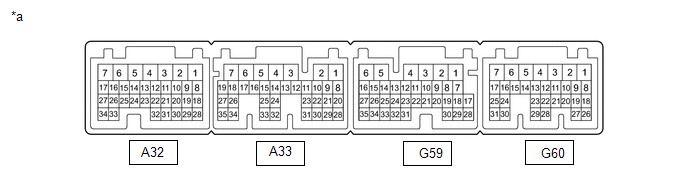
The standard normal voltage between each pair of hybrid vehicle control ECU terminals is shown in the table below. The appropriate conditions for checking each pair of terminals are also indicated. The result of checks should be compared with the standard normal voltage for that pair of terminals, displayed in the Specified Condition column. The illustration above can be used as a reference to identify the hybrid vehicle control ECU terminal locations.
Hybrid Vehicle Control ECU| Terminal No. (Symbol) | Wiring Color | Input/Output | Terminal Description | Condition | Specified Condition |
|---|---|---|---|---|---|
| A33-31 (HMCH) - G59-6 (E1) | B - W-B | IN/OUT | CAN communication signal | Power switch on (IG) | Pulse generation (Waveform 1) |
| A33-6 (MREL) - G59-6 (E1) | G - W-B | OUT | IGCT relay | Power switch on (IG) | 11 to 14 V |
| A32-17 (LIN3) - G59-6 (E1) | L - W-B | IN/OUT | LIN communication signal | Power switch on (READY) | Pulse generation |
| A33-30 (HMCL) - G59-6 (E1) | W - W-B | IN/OUT | CAN communication signal | Power switch on (IG) | Pulse generation (Waveform 1) |
(a) Oscilloscope waveforms
HINT:
Oscilloscope waveform samples are provided here for informational purposes. Noise and fluttering waveforms have been omitted.
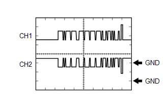
(1) Waveform 1 (CAN communication signal)
| Item | Content |
|---|---|
| Terminal | CH1: A33-31 (HMCH) - G59-6 (E1) CH2: A33-30 (HMCL) - G59-6 (E1) |
| Equipment Setting | 1 V/DIV., 50 μs./DIV. |
| Condition | Power switch on (IG) |
HINT:
The waveform will vary depending on the content of the digital communication (digital signal).
READ NEXT:
 How To Proceed With Troubleshooting
PROCEDURE 1. VEHICLE BROUGHT TO WORKSHOP
NEXT 2. CONFIRM PROBLEM SYMPTOMS
NEXT 3. CUSTOMER PROBLEM ANALYSIS (a) Check if the vehicle has be
System Diagram
SYSTEM DIAGRAM
Parts Location
PARTS LOCATION ILLUSTRATION *1 INVERTER WITH CONVERTER ASSEMBLY *2 COMPRESSOR WITH MOTOR ASSEMBLY *3 AUXILIARY BATTERY *4 FUSIBLE LINK BLOCK ASSEMBLY - BATT-S FUSE *5 BATTERY
SEE MORE:
Data Signal Circuit between Radio Receiver and Stereo Jack Adapter
DESCRIPTION The No. 1 stereo jack adapter assembly sends the sound data signal or image data signal from a USB device to the radio receiver assembly via this circuit. WIRING DIAGRAM PROCEDURE 1. CHECK HARNESS AND CONNECTOR (RADIO RECEIVER ASSEMBLY - NO. 1 STEREO JACK ADAPTER ASSEMBLY) (a)
Disassembly
DISASSEMBLY PROCEDURE 1. REMOVE HOOD CUSHION CENTER (a) Using a clip remover, disengage the 10 hood to cowl top seal clips to remove the hood cushion center. (b) Remove the 10 hood to cowl top seal clips from the hood cushion center. 2. REMOVE HOOD INSULATOR (a) for TMK Made: (1) U
