Lexus ES: Parts Location
Lexus ES (XZ10) Service Manual / Power Source & Network / A25a-fxs (battery / Charging) / Charging System / Parts Location
PARTS LOCATION
ILLUSTRATION
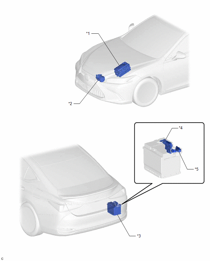
| *1 | INVERTER WITH CONVERTER ASSEMBLY | *2 | COMPRESSOR WITH MOTOR ASSEMBLY |
| *3 | AUXILIARY BATTERY | *4 | FUSIBLE LINK BLOCK ASSEMBLY - BATT-S FUSE |
| *5 | BATTERY STATE SENSOR ASSEMBLY | - | - |
ILLUSTRATION
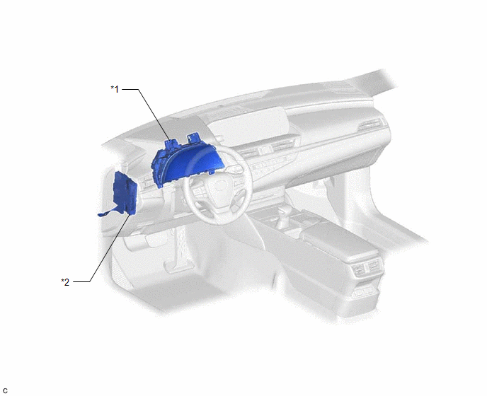
| *1 | COMBINATION METER ASSEMBLY | *2 | HYBRID VEHICLE CONTROL ECU |
READ NEXT:
 Precaution
PRECAUTION CHARGING SYSTEM PRECAUTION CAUTION:
Orange wire harnesses and connectors indicate high-voltage circuits. To prevent electric shock, always follow the procedure described in the repair ma
Installation
INSTALLATION PROCEDURE 1. INSTALL BATTERY STATE SENSOR ASSEMBLY (a) Engage the 2 claws to install the battery state sensor assembly to the battery current sensor holder. (b) Connect the battery state
SEE MORE:
Components
COMPONENTS ILLUSTRATION *1 FUEL SUCTION PLATE SUB-ASSEMBLY *2 NO. 1 FUEL SUCTION SUPPORT *3 FUEL FILTER - -
Components
COMPONENTS ILLUSTRATION *A for Driver Side *B for Front Passenger Side *C for 17 Speakers - - *1 COURTESY LIGHT ASSEMBLY *2 FRONT DOOR TRIM BOARD SUB-ASSEMBLY *3 FRONT NO. 1 SPEAKER ASSEMBLY *4 FRONT NO. 4 SPEAKER ASSEMBLY *5 MULTIPLEX NETWORK MASTER SWI
© 2016-2026 Copyright www.lexguide.net
