Lexus ES: Disassembly
DISASSEMBLY
PROCEDURE
1. REMOVE HOOD CUSHION CENTER
| (a) Using a clip remover, disengage the 10 hood to cowl top seal clips to remove the hood cushion center. |
|
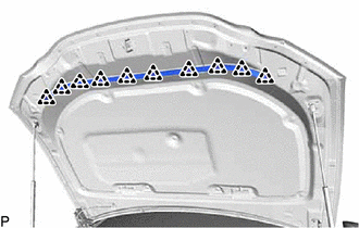
(b) Remove the 10 hood to cowl top seal clips from the hood cushion center.
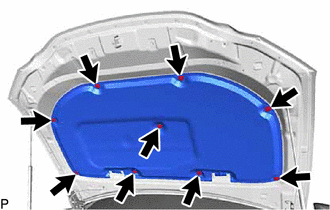
2. REMOVE HOOD INSULATOR
(a) for TMK Made:
| (1) Using a clip remover, remove the 9 hood insulator clips. |
|
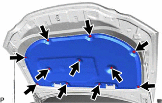
(b) for TMMK Made:
| (1) Using a clip remover, remove the 11 hood insulator clips. |
|
(c) Disengage the 2 guides to remove the hood insulator as shown in the illustration.
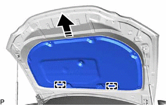
.png) | Remove in this Direction |
3. REMOVE WASHER NOZZLE SUB-ASSEMBLY
Click here .gif)
HINT:
Use the same procedure as for the LH side.
4. DISCONNECT WASHER HOSE ASSEMBLY
| (a) Disengage the 5 clamps. |
|
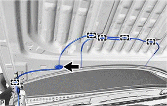
(b) Disengage the grommet to disconnect the washer hose assembly.
5. REMOVE HOOD SUPPORT ASSEMBLY LH
Click here
6. REMOVE HOOD SUPPORT ASSEMBLY RH
HINT:
Use the same procedure as for the LH side.
7. REMOVE HOOD STAY BRACKET LH
Click here
8. REMOVE HOOD STAY BRACKET RH
HINT:
Use the same procedure as for the LH side.
READ NEXT:
 Adjustment
ADJUSTMENT CAUTION / NOTICE / HINT *a Centering Bolt *b Standard Bolt HINT:
Centering bolts are used to install the hood hinges and hood lock. The hood and hood lock cannot be adjust
Reassembly
REASSEMBLY PROCEDURE 1. INSTALL HOOD STAY BRACKET LH Click here 2. INSTALL HOOD STAY BRACKET RH HINT: Use the same procedure as for the LH side. 3. INSTALL HOOD SUPPORT ASSEMBLY LH Click here 4. I
SEE MORE:
On-vehicle Inspection
ON-VEHICLE INSPECTION PROCEDURE 1. INSPECT HOOD SUB-ASSEMBLY (a) Check that the clearance measurements of areas a through d are within each standard range. Standard Clearance Area Measurement Area Measurement a 2.85 to 5.85 mm (0.112 to 0.230 in.) b 1.85 to 5.85 mm (0.0728 to 0.2
Wiper Switch Signal Mismatch between LIN and Line (B1372)
DESCRIPTION Under normal operation, the windshield wiper motor assembly receives operation signals from the windshield wiper switch assembly via LIN communication. The windshield wiper motor assembly and windshield wiper switch assembly are also connected via direct line in order to operate the fron
