Lexus ES: System Diagram
Lexus ES (XZ10) Service Manual / Power Source & Network / A25a-fxs (battery / Charging) / Charging System / System Diagram
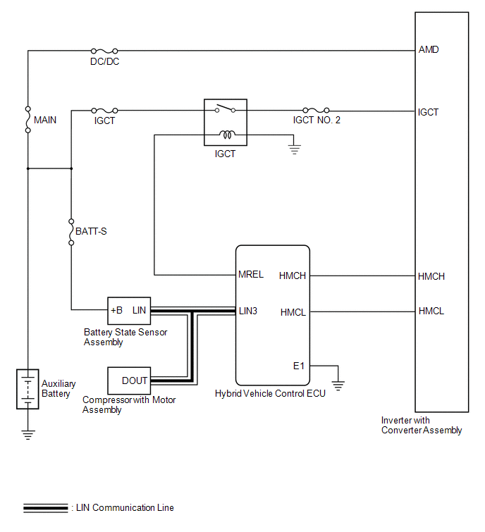
SYSTEM DIAGRAM
READ NEXT:
 Parts Location
PARTS LOCATION ILLUSTRATION *1 INVERTER WITH CONVERTER ASSEMBLY *2 COMPRESSOR WITH MOTOR ASSEMBLY *3 AUXILIARY BATTERY *4 FUSIBLE LINK BLOCK ASSEMBLY - BATT-S FUSE *5 BATTERY
Precaution
PRECAUTION CHARGING SYSTEM PRECAUTION CAUTION:
Orange wire harnesses and connectors indicate high-voltage circuits. To prevent electric shock, always follow the procedure described in the repair ma
SEE MORE:
System Diagram
SYSTEM DIAGRAM Transmitting ECU (Transmitter) Receiving ECU Signal Communication Method Skid control ECU (brake actuator assembly) Steering angle sensor Steering angle sensor request signal CAN communication line Steering angle sensor Skid control ECU (brake actuator a
Components
COMPONENTS ILLUSTRATION *A for Driver Side *B for Front Passenger Side *1 COURTESY LIGHT ASSEMBLY *2 FRONT DOOR TRIM BOARD SUB-ASSEMBLY *3 MULTIPLEX NETWORK MASTER SWITCH ASSEMBLY WITH FRONT DOOR UPPER ARMREST BASE PANEL *4 NO. 2 DOOR TRIM PAD *5 POWER WINDOW REGU
© 2016-2026 Copyright www.lexguide.net
