Lexus ES: System Diagram
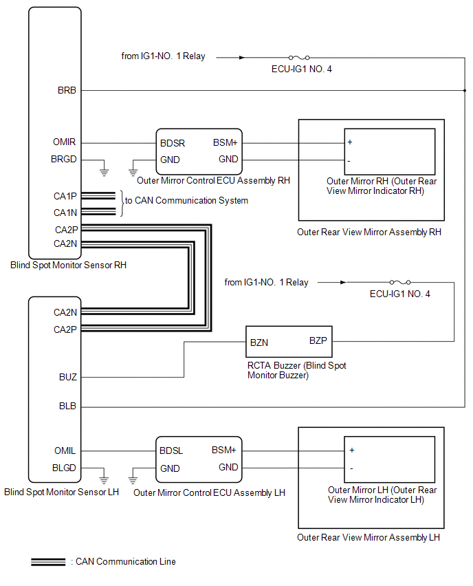
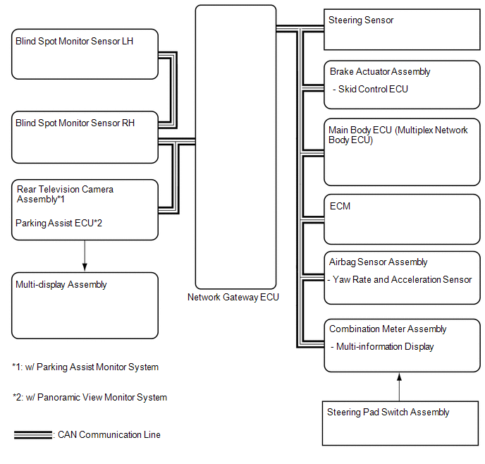
SYSTEM DIAGRAM
READ NEXT:
 Terminals Of Ecu
TERMINALS OF ECU BLIND SPOT MONITOR SENSOR RH Terminal No. (Symbol) Wiring Color Terminal Description Condition Specified Condition R4-4 (OMIR) - R4-10 (BRGD) SB - W-B Outer rear v
Lost Communication with ECM / PCM "A" (U0100,U0125,U0126,U0129,U0142,U0293)
DESCRIPTION These DTCs are stored if there is a malfunction in the CAN communication system connected to the blind spot monitor sensor. HINT: If CAN communication system DTCs are stored, they may also
Lost Communication with Blind Spot Monitor Slave Module (U0232)
DESCRIPTION This DTC is stored when the blind spot monitor sensor RH judges that there is a communication problem with the blind spot monitor sensor LH. DTC No. Detection Item DTC Detection Con
SEE MORE:
Parts Location
PARTS LOCATION ILLUSTRATION *1 BRAKE ACTUATOR ASSEMBLY - SKID CONTROL ECU *2 ECM *3 FRONT SPEED SENSOR LH *4 FRONT SPEED SENSOR RH *5 REAR SKID CONTROL SENSOR LH *6 REAR SKID CONTROL SENSOR RH *7 TRANSMISSION COUPLING ASSEMBLY - 4WD LINEAR SOLENOID - - ILLU
Illumination for Panel Switch does not Come on with Tail Switch ON
CAUTION / NOTICE / HINT NOTICE:
Depending on the parts that are replaced during vehicle inspection or maintenance, performing initialization, registration or calibration may be needed. Refer to Precaution for Audio and Visual System.
Click here
When replacing the radio receiver assembly, alw
© 2016-2026 Copyright www.lexguide.net
