Lexus ES: Removal
REMOVAL
CAUTION / NOTICE / HINT
The necessary procedures (adjustment, calibration, initialization or registration) that must be performed after parts are removed and installed, or replaced during front crankshaft oil seal removal/installation are shown below.
Necessary Procedure After Parts Removed/Installed/Replaced| Replaced Part or Performed Procedure | Necessary Procedure | Effect/Inoperative Function when Necessary Procedure not Performed | Link |
|---|---|---|---|
| Battery terminal is disconnected/reconnected | Perform steering sensor zero point calibration | Lane Control System | |
| Pre-collision System | |||
| Parking Support Brake System*1 | |||
| Lighting System | |||
| Memorize steering angle neutral point | Parking Assist Monitor System | | |
| Panoramic View Monitor System | | ||
| Initialize power trunk lid system | Power Trunk Lid System | | |
| Replacement of ECM | Vehicle Identification Number (VIN) registration | MIL comes on | |
| ECU communication ID registration (Immobiliser system) | Engine start function | | |
| Gas leak from exhaust system is repaired | Inspection after repair |
| |
| Replacement of automatic transaxle assembly |
|
| for Initialization: for Registration: |
| Replacement of ECM (If transaxle compensation code read from ECM) |
| ||
| Replacement of ECM (If transaxle compensation code not read from ECM) |
| ||
| Replacement of ECM | Code registration (Smart access system with push-button start (for Start Function, Gasoline Model) |
| |
| Replacement of automatic transaxle fluid | ATF thermal degradation estimate reset | The value of the Data List item "ATF Thermal Degradation Estimate" is not estimated correctly | |
| Suspension, tires, etc. (The vehicle height changes because of suspension or tire replacement) | Rear television camera assembly optical axis adjustment (Back camera position setting) | Parking assist monitor system | for Initialization: for Calibration: |
| Perform headlight ECU sub-assembly LH initialization | Lighting system | | |
| Front wheel alignment adjustment |
|
| |
| Front television camera view adjustment | Panoramic View Monitor System | for Initialization for Calibration |
| Replacement of front bumper assembly |
|
| |
-
*1: When performing learning using the Techstream.
Click here
.gif)
- *2: Not necessary when ECM replaced with new one
NOTICE:
- After the engine switch is turned off, the radio receiver assembly records various types of memory and settings. As a result, after turning the engine switch off, make sure to wait at least 85 seconds before disconnecting the cable from the negative (-) battery terminal. (for Audio and Visual System)
- After the engine switch is turned off, the radio receiver assembly records various types of memory and settings. As a result, after turning the engine switch off, make sure to wait at least 85 seconds before disconnecting the cable from the negative (-) battery terminal. (for Navigation System)
PROCEDURE
1. REMOVE ENGINE ASSEMBLY WITH TRANSAXLE
Click here
2. REMOVE V-RIBBED BELT
Click here
3. REMOVE CRANKSHAFT PULLEY
(a) Using SST to hold the crankshaft pulley, loosen the crankshaft pulley set bolt. Further loosen the crankshaft pulley set bolt until 2 or 3 threads remain screwed into the crankshaft.
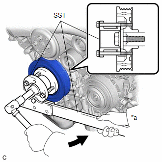
| *a | Hold |
.png) | Turn |
SST: 09213-70011
09213-70020
SST: 09330-00021
(b) Using SST, remove the crankshaft pulley set bolt and crankshaft pulley.
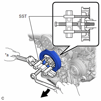
| *a | Hold |
| | Turn |
SST: 09950-50013
09951-05010
09952-05010
09953-05020
09954-05021
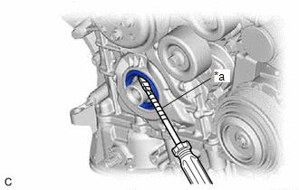
4. REMOVE TIMING CHAIN CASE OIL SEAL
| (a) Using a screwdriver with its tip wrapped with protective tape, pry out the timing chain case oil seal. NOTICE: After removal, check the crankshaft for damage. If it is damaged, smooth the surface with 400-grit sandpaper. |
|
READ NEXT:
 Installation
INSTALLATION PROCEDURE 1. INSTALL TIMING CHAIN CASE OIL SEAL (a) Apply MP grease to the lip of a new timing chain case oil seal. *a Oil Seal Protrusion Height (b) Using SST
Components
COMPONENTS ILLUSTRATION *1 REAR ENGINE OIL SEAL *2 NO. 1 CRANKSHAFT POSITION SENSOR PLATE *3 DRIVE PLATE AND RING GEAR SUB-ASSEMBLY *4 REAR DRIVE PLATE SPACER N*m (kgf*cm, f
SEE MORE:
System Diagram
SYSTEM DIAGRAM Communication Table Sender Receiver Signal Line Certification ECU (Smart Key ECU Assembly) Main Body ECU (Multiplex Network Body ECU) Luggage compartment door lock assembly open operation signal CAN
Motor Electronics Coolant Temperature Sensor Circuit Voltage Out of Range (P0A001C)
DTC SUMMARY MALFUNCTION DESCRIPTION These DTCs indicate that the temperature sensor value is abnormal. The cause of this malfunction may be one of the following: Area Main Malfunction Description Inverter low-voltage circuit The connectors are not connected properly Hybrid cooling sys
