Lexus ES: System Diagram
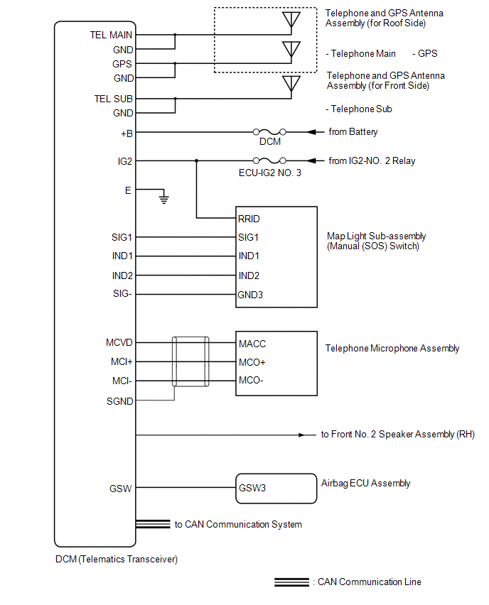
SYSTEM DIAGRAM
READ NEXT:
 Terminals Of Ecu
TERMINALS OF ECU Terminal No. (Symbol) Wiring Color Terminal Description Condition Specified Condition G128-1 (+B) - G128-20 (E) BR - W-B Power source (+B) Always 11 to 14 V
Unable To Connect To Call Center
DESCRIPTION This may occur when the intensity of telephone radio frequency was very weak, or the safety connect system has a malfunction and a DTC is set. PROCEDURE 1. CHECK COMMUNICATION SERVIC
Vehicle Control History
VEHICLE CONTROL HISTORY NOTICE: Make sure to record any output Vehicle Control History codes before clearing them and checking the Vehicle Control History again. CHECK VEHICLE CONTROL HISTORY NOTICE:
SEE MORE:
Lost Communication With Body Control Module "B" (U0142)
DESCRIPTION DTC No. Detection Item DTC Detection Condition Trouble Area U0142 Lost Communication with Main Body ECU No communication with main body ECU (multiplex network body ECU)
CAN communication system
Main body ECU (multiplex network body ECU)
PROCEDURE 1. GO
Slave Module Horizontal Axis Misalignment (C1AC2)
DESCRIPTION This DTC is stored when the angle of the blind spot monitor sensor LH deviates more than the allowable range from the horizontal axis. HINT:
If a drum tester such as a speedometer tester, brake/speedometer combination tester or chassis dynamometer is used with the blind spot monitor s
© 2016-2026 Copyright www.lexguide.net
