Lexus ES: System Diagram
SYSTEM DIAGRAM
w/ Navigation System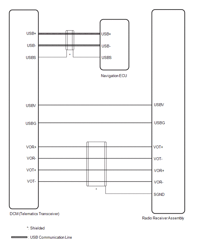
READ NEXT:
 Terminals Of Ecu
TERMINALS OF ECU DCM (TELEMATICS TRANSCEIVER) *a to Telephone Antenna (Sub) *b to GPS Antenna *c to Telephone Antenna (Main) - - Terminal No. (Symbol) Wiring Color Termin
Confirm Cellular Phone Functionality
PROCEDURE 1. CHECK CUSTOMER'S CELLULAR PHONE COMPATIBILITY (a) Check if the cellular phone is compatible (Refer to http://www.lexus.com/MobileLink/). Result Proceed to Cellular phone
SEE MORE:
Driver Side Power Window does not Operate with Power Window Master Switch
DESCRIPTION When the power switch is on (IG), the power window regulator motor assembly (for driver door) is operated by the multiplex network master switch assembly. The power window regulator motor assembly (for driver door) has motor, regulator and ECU functions. WIRING DIAGRAM CAUTION / NOTICE
Lost Communication with Hybrid Powertrain Control Module (Hybrid/EV Battery Local Bus) Missing Message (U115087)
DESCRIPTION The battery ECU assembly transmits and receives signals via CAN communication to and from the hybrid vehicle control ECU. DTC No. Detection Item DTC Detection Condition Trouble Area MIL Warning Indicate U115087 Lost Communication with Hybrid Powertrain Control Module (
© 2016-2026 Copyright www.lexguide.net
