Lexus ES: Terminals Of Ecu
TERMINALS OF ECU
DCM (TELEMATICS TRANSCEIVER)
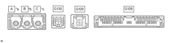
| *a | to Telephone Antenna (Sub) | *b | to GPS Antenna |
| *c | to Telephone Antenna (Main) | - | - |
| Terminal No. (Symbol) | Wiring Color | Terminal Description | Condition | Specified Condition |
|---|---|---|---|---|
| G130-1 (USB-) | - | USB communication line | - | - |
| G130-2 (USB+) | - | USB communication line | - | - |
| G130-3 (USBS) - Body ground | Shielded - Body ground | Shield ground | Always | Below 1 V |
| G128-31 (USBG) - Body ground | G - Body ground | DCM (Telematics Transceiver) power supply ground signal | Always | Below 1 V |
| G128-17 (VOT+) - G128-20 (E) | B - W-B | Sent voice signal | Calling while using the operator service | A waveform synchronized with the voice signals received voice is output |
| G128-15 (USBV) - G128-20 (E) | B - W-B | DCM (Telematics Transceiver) power supply signal | Engine switch off | Below 1 V |
| Engine switch on (IG) | 4.5 to 5.25 V | |||
| G128-33 (VOT-) - G128-20 (E) | W - W-B | Sent voice signal | Calling while using the operator service | A waveform synchronized with the received voice is output |
| G128-34 (VOR-) - G128-20 (E) | G - W-B | Receive voice signal | Receiving a call while using the operator service | A waveform synchronized with the sent voice is output |
| G128-18 (VOR+) - G128-20 (E) | R - W-B | Receive voice signal | Receiving a call while using the operator service | A waveform synchronized with the sent voice is output |
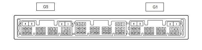
RADIO RECEIVER ASSEMBLY
| Terminal No. (Symbol) | Wiring Color | Terminal Description | Condition | Specified Condition |
|---|---|---|---|---|
| G1-15 (VOT+) - G5-1 (GND1) | R - W-B | Sent voice signal | Destination assist service in use and vehicle occupant speaking to operator | A waveform synchronized with the sent voice is output |
| G1-10 (USBV) - G5-1 (GND1) | B - W-B | DCM (Telematics transceiver) power supply | Engine switch on (ACC) | 4.75 to 5.25 V |
| Engine switch off | A waveform synchronized with sound is output | |||
| G1-11 (USBG) - G5-1 (GND1) | G - W-B | DCM (Telematics Transceiver) power supply ground signal | Always | Below 1 V |
| G1-12 (SGND) - Body ground | Shielded - Body ground | Shield ground | Always | Below 1 V |
| G1-13 (VOR+) - G5-1 (GND1) | B - W-B | Receive voice signal | Destination assist service in use and operator speaking to vehicle occupant | A waveform synchronized with the received voice is output |
| G1-14 (VOR-) - G5-1 (GND1) | W - W-B | Receive voice signal | Destination assist service in use and operator speaking to vehicle occupant | A waveform synchronized with the received voice is output |
| G1-16 (VOT-) - G5-1 (GND1) | G - W-B | Sent voice signal | Destination assist service in use and vehicle occupant speaking to operator | A waveform synchronized with the sent voice is output |
NAVIGATION ECU (w/ Navigation System)

| Terminal No. (Symbol) | Wiring Color | Terminal Description | Condition | Specified Condition |
|---|---|---|---|---|
| G108-2 (USB-) | - | USB communication line | - | - |
| G108-1 (USB+) | - | USB communication line | - | - |
| G108-3 (USBS) - Body ground | Shielded - Body ground | Shield ground | Always | Below 1 V |
READ NEXT:
 Confirm Cellular Phone Functionality
PROCEDURE 1. CHECK CUSTOMER'S CELLULAR PHONE COMPATIBILITY (a) Check if the cellular phone is compatible (Refer to http://www.lexus.com/MobileLink/). Result Proceed to Cellular phone
Confirm Vehicle Headunit Functionality
PROCEDURE 1. CHECK CUSTOMER'S CELLULAR PHONE COMPATIBILITY (a) Check if the cellular phone is compatible (Refer to http://www.lexus.com/MobileLink/). Result Proceed to Cellular phone
SEE MORE:
Installation
INSTALLATION PROCEDURE 1. INSTALL TURN SIGNAL SWITCH (a) Engage the claw as shown in the illustration. Install in this Direction (b) Install the turn signal switch with the 2 screws. 2. INSTALL UPPER STEERING COLUMN COVER Click here 3. INSTALL LOWER STEERING COLUMN COVER SUB-ASSEMBLY Cli
Left Headlight ECU Variation Error (B2456)
DESCRIPTION This DTC is stored if the headlight ECU sub-assembly LH for another destination is installed. AFS*1 DTC No. Detection Item DTC Detection Condition Trouble Area DTC Output from B2456 Left Headlight ECU Variation Error
The power switch is on (IG).
Vehicle specif
