Lexus ES: System Diagram
SYSTEM DIAGRAM
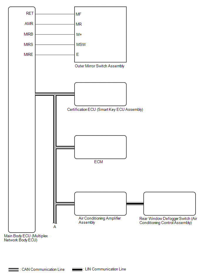
 Communication Table
 | Sender | Receiver | Signal | Line |
|---|---|---|---|
| Main Body ECU (Multiplex Network Body ECU) | Outer Mirror Control ECU Assembly |
| CAN |
| Outer Mirror Control ECU Assembly | Main Body ECU (Multiplex Network Body ECU) |
| CAN |
| Certification ECU (Smart Key ECU Assembly) | Main Body ECU (Multiplex Network Body ECU) | Key ID signal | CAN |
| Air Conditioning Amplifier Assembly | Outer Mirror Control ECU Assembly | Mirror heater drive request signal | CAN |
| ECM | Main Body ECU (Multiplex Network Body ECU) | Reverse signal | CAN |
| Rear Window Defogger switch (Air Conditioning Control Assembly) | Air Conditioning Amplifier Assembly | Mirror heater switch (rear window defogger switch) operation signal | LIN |
READ NEXT:
 How To Proceed With Troubleshooting
CAUTION / NOTICE / HINT HINT:
Use the following procedure to troubleshoot the power mirror control system (w/ Memory).
*: Use the Techstream.
PROCEDURE 1. VEHICLE BROUGHT TO WORKSHOP
Customize Parameters
CUSTOMIZE PARAMETERS CUSTOMIZE POWER MIRROR CONTROL SYSTEM (w/ Memory) NOTICE:
When the customer requests a change in a function, first make sure that the function can be customized.
Record the c
Operation Check
OPERATION CHECK CHECK ELECTRICAL REMOTE CONTROL MIRROR FUNCTION (a) Turn the engine switch on (IG). (b) b. With the mirror select switch driver side switch on, check that the outer rear view mirror as
SEE MORE:
Motor Shutdown Stuck Off (P1C6A9F)
DTC SUMMARY MALFUNCTION DESCRIPTION The hybrid vehicle control ECU detects malfunctions which prevent the motor (MG2) inverter shutdown circuit shutting down the hybrid vehicle control system. Detection is performed during the shutdown sequence when the power switch is turned off. If motor (MG2) inv
Drive Motor "A" Phase U-V-W Current Sensor Signal Compare Failure (P0BFD62,P1C671F)
DTC SUMMARY MALFUNCTION DESCRIPTION These DTCs indicate that the current sensor value is abnormal. The cause of this malfunction may be one of the following: Internal inverter malfunction
Current sensor malfunction
Inverter with converter assembly internal circuit malfunction
DESCRIPTION
© 2016-2026 Copyright www.lexguide.net
