Lexus ES: System Diagram
SYSTEM DIAGRAM
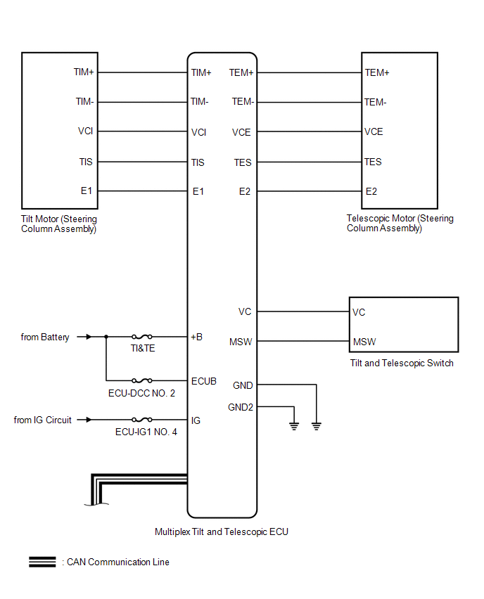
.png) Communication Table
Communication Table | Transmitting ECU (Transmitter) | Receiving ECU | Signal | Communication Method |
|---|---|---|---|
| Main Body ECU (Multiplex Network Body ECU) | Multiplex Tilt and Telescopic ECU |
| CAN |
| Position Control ECU Assembly (Driver Seat) | Multiplex Tilt and Telescopic ECU |
| |
| Combination Meter Assembly | Multiplex Tilt and Telescopic ECU | Vehicle speed signal | |
| Multiplex Tilt and Telescopic ECU | Main Body ECU (Multiplex Network Body ECU) | State signal of tilt and telescopic steering | |
| Multiplex Tilt and Telescopic ECU | Position Control ECU Assembly (Driver Seat) |
| |
| Tilt and Telescopic Switch | Multiplex Tilt and Telescopic ECU | Tilt and Telescopic Switch signal | Direct line |
READ NEXT:
 System Description
SYSTEM DESCRIPTION FUNCTION OF MAIN COMPONENTS Component Function Multiplex tilt and telescopic ECU This ECU sends a control signal to the tilt motor (steering column assembly) and telescop
How To Proceed With Troubleshooting
CAUTION / NOTICE / HINT HINT: *: Use the Techstream. PROCEDURE 1. VEHICLE BROUGHT TO WORKSHOP
NEXT 2. INSPECT BATTERY VOLTAGE (a) Measure the battery voltage with th
Customize Parameters
CUSTOMIZE PARAMETERS CUSTOMIZE POWER TILT AND POWER TELESCOPIC STEERING COLUMN SYSTEM HINT: The following items can be customized. NOTICE:
When the customer requests a change in a function, first m
SEE MORE:
Components
COMPONENTS ILLUSTRATION *1 NO. 1 OIL COOLER OUTLET TUBE SUB-ASSEMBLY *2 NO. 1 TRANSMISSION OIL FILLER TUBE *3 OIL COOLER UNION SUB-ASSEMBLY *4 OVERFLOW PLUG *5 PARK/NEUTRAL POSITION SWITCH ASSEMBLY *6 REFILL PLUG *7 TRANSMISSION CONTROL SHAFT LEVER *8 GASKET
Components
COMPONENTS ILLUSTRATION *1 UPPER HV BATTERY COVER SUB-ASSEMBLY *2 BATTERY VOLTAGE SENSOR *3 NO. 1 HV BATTERY SHIELD PANEL - - N*m (kgf*cm, ft.*lbf): Specified torque - -
© 2016-2026 Copyright www.lexguide.net
