Lexus ES: System Diagram
Lexus ES (XZ10) Service Manual / Power Source & Network / A25a-fks (battery / Charging) / Charging System / System Diagram
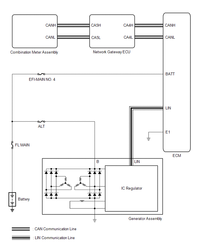
SYSTEM DIAGRAM
READ NEXT:
 Parts Location
PARTS LOCATION ILLUSTRATION *1 GENERATOR ASSEMBLY *2 ECM *3 NO. 1 ENGINE ROOM RELAY BLOCK AND NO. 1 JUNCTION BLOCK ASSEMBLY - - ILLUSTRATION *1 COMBINATION METER ASSEMBLY
Precaution
PRECAUTION INITIALIZATION NOTICE: Make sure to perform the necessary procedures (adjustment, calibration, initialization, or registration) after parts related to the cable has been disconnected from t
Battery
ComponentsCOMPONENTS ILLUSTRATION *1 BATTERY *2 NEGATIVE BATTERY TERMINAL *3 POSITIVE BATTERY TERMINAL *4 NO. 2 BATTERY CLAMP *5 BATTERY TERMINAL CAP *6 BATTERY INSULATO
SEE MORE:
Engine Circuit Malfunction (C1280)
DESCRIPTION If a malfunction in the ECM circuit occurs, the 4WD ECU assembly will output this DTC. DTC No. Detection Item DTC Detection Condition Trouble Area C1280 Engine Circuit Malfunction When the following continues for 5 seconds or more:
Communication with ECM is operating
Parts Location
PARTS LOCATION ILLUSTRATION *1 SWING GRILLE ACTUATOR ASSEMBLY *2 RADIATOR SHUTTER SUB-ASSEMBLY *3 ECM - - ILLUSTRATION *1 COMBINATION METER ASSEMBLY *2 INSTRUMENT PANEL JUNCTION BLOCK ASSEMBLY - ECU-B NO. 2 FUSE *3 AIR CONDITIONING AMPLIFIER ASSEMBLY *4 HYB
© 2016-2026 Copyright www.lexguide.net
