Lexus ES: System Diagram
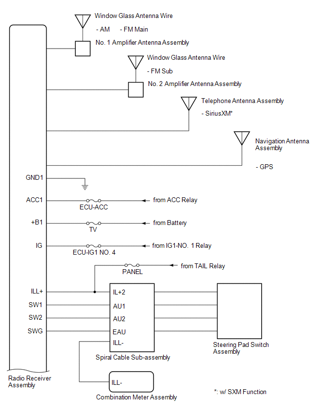
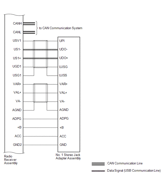
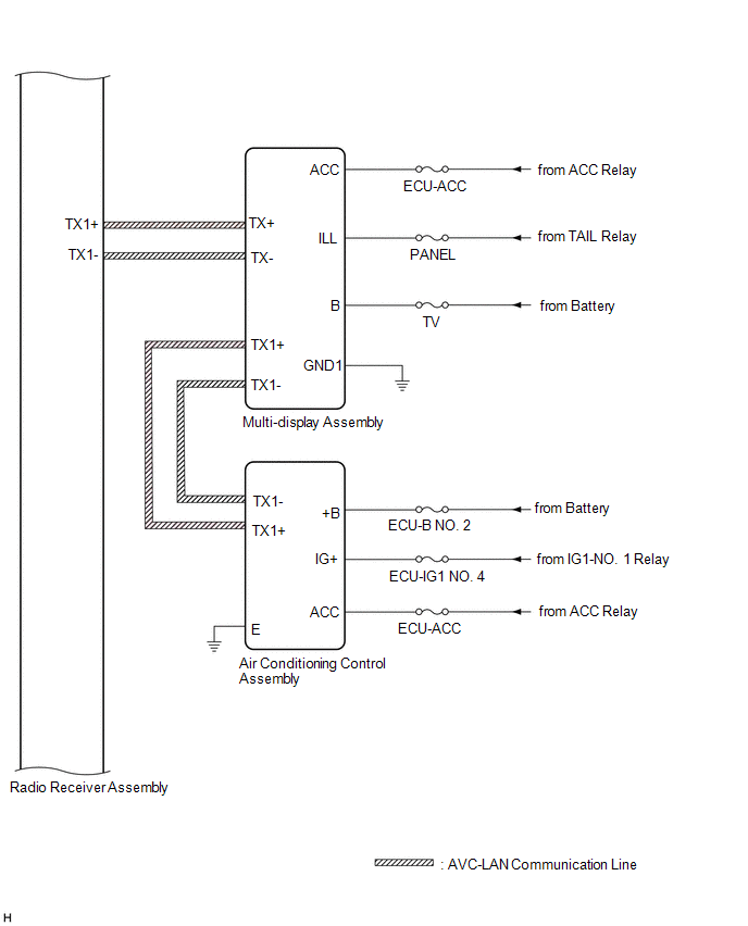
SYSTEM DIAGRAM
 w/ Parking Assist Monitor System
 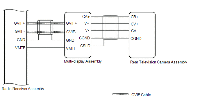 w/ Panoramic View Monitor System
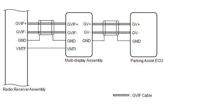
 w/ Manual (SOS) Switch
 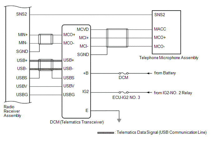 w/o Manual (SOS) Switch
 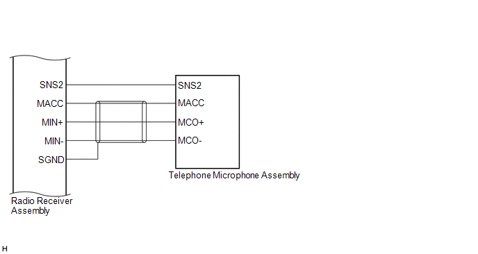 for 10 Speakers
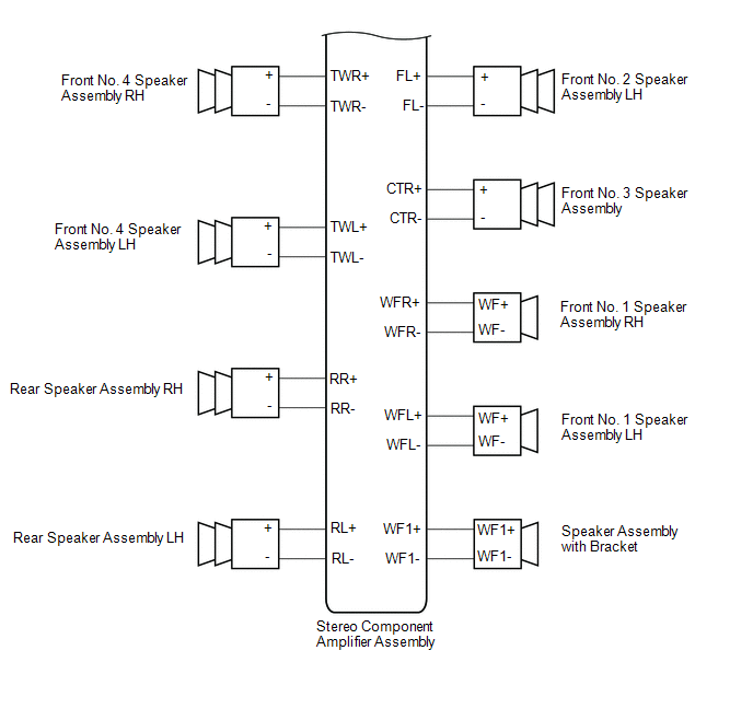
 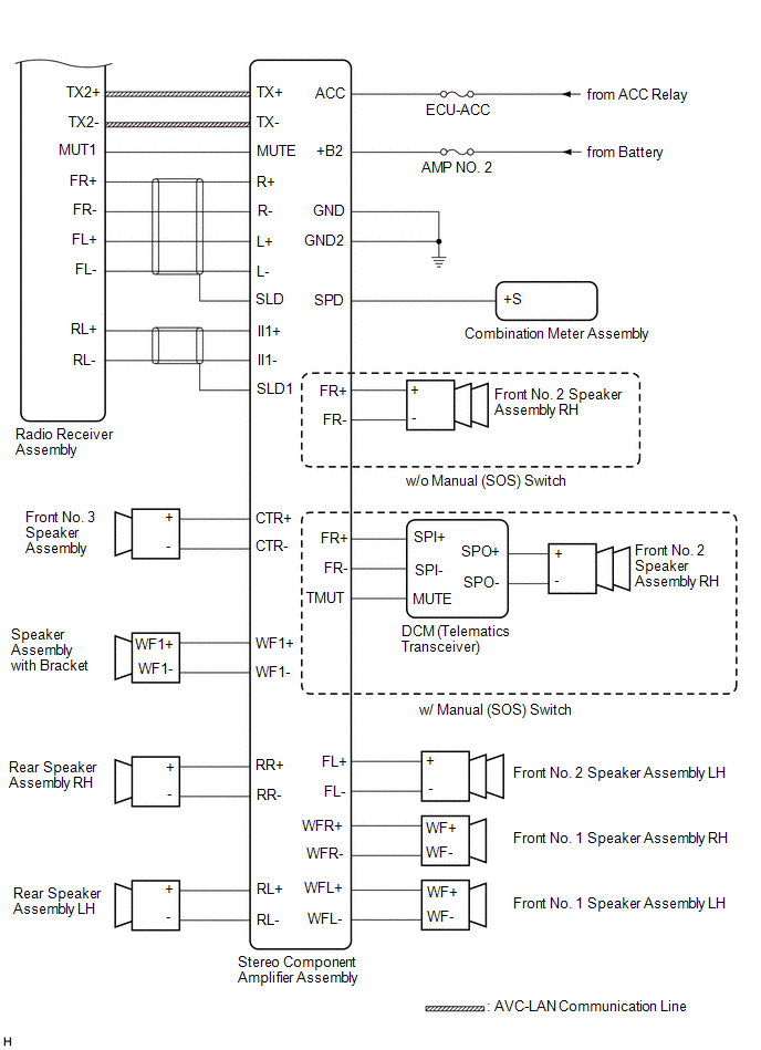 for 17 Speakers
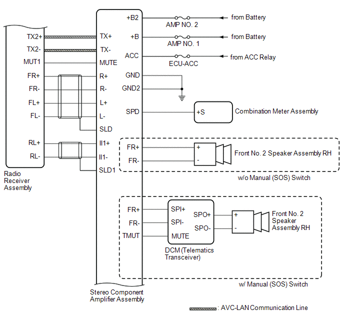
READ NEXT:
 Terminals Of Ecu
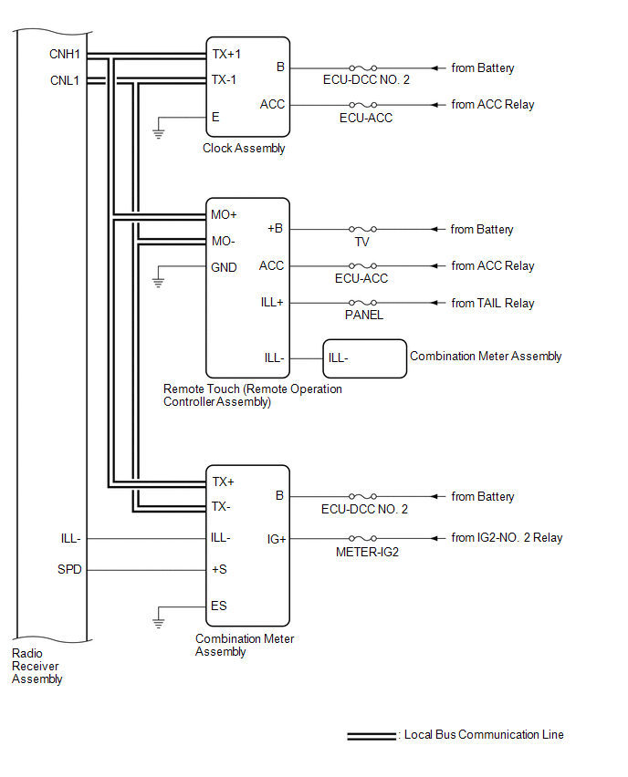
TERMINALS OF ECU HINT: Check from the rear of the connector while it is connected to the components. RADIO RECEIVER ASSEMBLY Terminal No. (Symbol) Wiring Color Terminal Description Condition
Sending Malfunction (Navigation to APGS) (U0073,U0100,U0129,U0140,U0155,U0164,U0198,U023B,U0265,U1110)
DESCRIPTION These DTCs are stored when a malfunction occurs in the CAN communication circuit. DTC No. Detection Item DTC Detection Condition Trouble Area U0073 Sending Malfunction (Navi
USB Audio System Recognition/Play Error
DESCRIPTION When a USB device or "iPod" is connected to the USB jack of the No. 1 stereo jack adapter assembly, it must have playable files. The device must also communicate with and be recognized by
SEE MORE:
System Diagram
SYSTEM DIAGRAM HINT: See the layout drawing to confirm the locations and tightening torque of flexible hoses and brake lines. *A for HV Model - - *1 Brake Booster with Master Cylinder Assembly *2 Brake Actuator Assembly *3 Brake Booster Pump Assembly - - *a Brake
FR Speed Sensor Wrong Installation (X0452)
DESCRIPTION Code Tester Display Measurement Item Trouble Area X0452 FR Speed Sensor Wrong Installation History of front speed sensor RH being installed incorrectly Front Speed Sensor RH PROCEDURE 1. CHECK FOR DTCs (HEALTH CHECK) (a) Perform the Health Check using the T
© 2016-2026 Copyright www.lexguide.net
