Lexus ES: USB Audio System Recognition/Play Error
DESCRIPTION
When a USB device or "iPod" is connected to the USB jack of the No. 1 stereo jack adapter assembly, it must have playable files. The device must also communicate with and be recognized by the radio receiver assembly. This diagnostic procedure is for when a device is not recognized, or files from the device cannot be played normally.
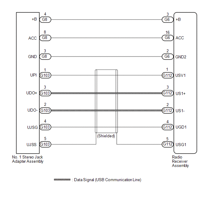
WIRING DIAGRAM
CAUTION / NOTICE / HINT
NOTICE:
-
Depending on the parts that are replaced during vehicle inspection or maintenance, performing initialization, registration or calibration may be needed. Refer to Precaution for Audio and Visual System.
Click here
.gif)
-
When replacing the radio receiver assembly, always replace it with a new one. If a radio receiver assembly which was installed to another vehicle is used, the following may occur:
- A communication malfunction DTC may be stored.
- The radio receiver assembly may not operate normally.
HINT:
- When a large amount of data is in a USB device, it may take a while to begin playback.
- When using a USB device, files that are protected by copyright cannot be played.
-
When files are not played in the sorted order, perform the following procedure before inspection.
- Add numbers in front of the file names.
- Put the files in a folder and copy the folder data to the USB device.
PROCEDURE
| 1. | CHECK USB DEVICE OR "iPod" |
(a) Disconnect the USB device or "iPod" from the No. 1 stereo jack adapter assembly.
(b) Check if playable files are present on the USB device or "iPod".
HINT:
Refer to System Description for playable files.
Click here
(c) Check if the USB device is a compatible format or "iPod" is a compatible version.
HINT:
Refer to System Description for compatible formats and versions.
Click here
| Result | Proceed to |
|---|---|
| No playable files exist, or incompatible device format or version. | A |
| Playable files exist, and compatible device format or version. | B |
| A | .gif) | END (USB DEVICE FORMAT IS INCOMPATIBLE, "iPod" VERSION IS INCOMPATIBLE, OR NO PLAYABLE FILES EXIST) |
|
.gif)
| 2. | CHECK HARNESS AND CONNECTOR (RADIO RECEIVER ASSEMBLY - NO. 1 STEREO JACK ADAPTER ASSEMBLY) |
(a) Disconnect the G6 radio receiver assembly connector.
(b) Disconnect the G8 No. 1 stereo jack adapter assembly connector.
(c) Measure the resistance according to the value(s) in the table below.
Standard Resistance:
| Tester Connection | Condition | Specified Condition |
|---|---|---|
| G6-2 (GND2) - G8-3 (GND) | Always | Below 1 Ω |
| G6-3 (+B) - G8-4 (+B) | Always | Below 1 Ω |
| G6-16 (ACC) - G8-8 (ACC) | Always | Below 1 Ω |
| G6-2 (GND2) or G8-3 (GND) - Body ground | Always | 10 kΩ or higher |
| G6-3 (+B) or G8-4 (+B) - Body ground | Always | 10 kΩ or higher |
| G6-16 (ACC) or G8-8 (ACC) - Body ground | Always | 10 kΩ or higher |
| NG | | REPAIR OR REPLACE HARNESS OR CONNECTOR |
|
| 3. | CHECK HARNESS AND CONNECTOR (RADIO RECEIVER ASSEMBLY - NO. 1 STEREO JACK ADAPTER ASSEMBLY) |
| (a) Disconnect the G112 radio receiver assembly connector. |
|
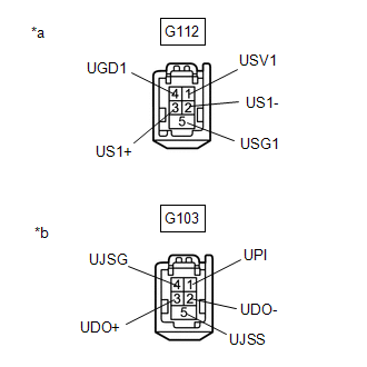
(b) Disconnect the G103 No. 1 stereo jack adapter assembly connector.
(c) Measure the resistance according to the value(s) in the table below.
Standard Resistance:
| Tester Connection | Condition | Specified Condition |
|---|---|---|
| G112-1 (USV1) - G103-1 (UPI) | Always | Below 1 Ω |
| G112-2 (US1-) - G103-2 (UDO-) | Always | Below 1 Ω |
| G112-3 (US1+) - G103-3 (UDO+) | Always | Below 1 Ω |
| G112-4 (UGD1) - G103-4 (UJSG) | Always | Below 1 Ω |
| G112-5 (USG1) - G103-5 (UJSS) | Always | Below 1 Ω |
| G112-1 (USV1) or G103-1 (UPI) - Body ground | Always | 10 kΩ or higher |
| G112-2 (US1-) or G103-2 (UDO-) - Body ground | Always | 10 kΩ or higher |
| G112-3 (US1+) or G103-3 (UDO+) - Body ground | Always | 10 kΩ or higher |
| G112-4 (UGD1) or G103-4 (UJSG) - Body ground | Always | 10 kΩ or higher |
| G112-5 (USG1) or G103-5 (UJSS) - Body ground | Always | 10 kΩ or higher |
| NG | | REPAIR OR REPLACE HARNESS OR CONNECTOR |
|
| 4. | CHECK RADIO RECEIVER ASSEMBLY (NO. 1 STEREO JACK ADAPTER ASSEMBLY POWER SOURCE) |
| (a) Disconnect the G103 and G8 No. 1 stereo jack adapter assembly connectors. |
|
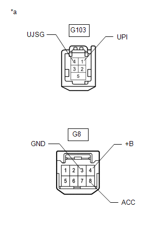
(b) Measure the voltage according to the value(s) in the table below.
Standard Voltage:
| Tester Connection | Condition | Specified Condition |
|---|---|---|
| G103-1 (UPI) - G103-4 (UJSG) | Engine switch on (ACC) | 4.5 to 5.5 V |
| G8-8 (ACC) - G8-3 (GND) | Engine switch on (ACC) | 11 to 14 V |
| G8-4 (+B) - G8-3 (GND) | Always | 11 to 14 V |
| NG | | REPLACE RADIO RECEIVER ASSEMBLY |
|
| 5. | FORMAT USB DEVICE OR RESTORE "iPod" AND RECHECK |
(a) Delete all files in the USB device or "iPod" and format/restore it.
(b) Save the data again and check if it can be played on the in-vehicle device.
NOTICE:
Formatting a USB device or restoring an "iPod" erases all music on the device. Ensure that backup music data is available before performing this operation.
OK:
Malfunction disappears.
| OK | | END |
|
| 6. | REPLACE USB DEVICE OR "iPod" |
(a) Turn the engine switch off.
HINT:
When this malfunction occurs, it is necessary to turn the engine switch off to make it possible for the vehicle to recognize a new device when it is connected.
(b) Turn the engine switch on (ACC).
(c) Connect a known good USB device or "iPod" to the No. 1 stereo jack adapter assembly.
HINT:
- If the malfunction occurred when a USB device was in use, use another USB device for the inspection. If the malfunction occurred when an "iPod" was in use, use another "iPod" for the inspection.
-
Refer to System Description for compatible formats and versions.
Click here
|
| 7. | CHECK USB DEVICE OR "iPod" |
(a) Check if a USB device or "iPod" is recognized by the radio receiver assembly, and if information such as track, artist and album names is displayed on the screen.
OK:
USB device or "iPod" is recognized properly and the information is displayed on the screen.
| OK | | USB DEVICE OR "iPod" WAS INCOMPATIBLE OR DEFECTIVE |
| NG | | PROCEED TO NEXT SUSPECTED AREA SHOWN IN PROBLEM SYMPTOMS TABLE |
READ NEXT:
 Vehicle Speed Signal Circuit between Stereo Component Amplifier and Combination Meter
DESCRIPTION The stereo component amplifier assembly receives a vehicle speed signal from the combination meter assembly to control the ASL function. HINT:
A voltage of 12 V or 5 V is output from ea
Visual Mute Signal Circuit between Radio Receiver and Multi-display
DESCRIPTION The radio receiver assembly sends a visual mute signal to the multi-display assembly. As a result, a black screen is displayed when the screen changes so that noise and distorted images ar
Voice Guidance Circuit between Radio Receiver and Stereo Component Amplifier
DESCRIPTION Using this circuit, the radio receiver assembly sends signals to the stereo component amplifier assembly. WIRING DIAGRAM PROCEDURE 1. CHECK HARNESS AND CONNECTOR (RADIO RECEIVER ASS
SEE MORE:
Parts Location
PARTS LOCATION ILLUSTRATION *1 FORWARD RECOGNITION CAMERA *2 BRAKE BOOSTER WITH MASTER CYLINDER ASSEMBLY - SKID CONTROL ECU *3 RACK AND PINION POWER STEERING GEAR ASSEMBLY - POWER STEERING ECU -POWER STEERING MOTOR -TORQUE SENSOR *4 NO. 1 ENGINE ROOM RELAY BLOCK AND NO. 1 JUNCTIO
Installation
INSTALLATION CAUTION / NOTICE / HINT HINT:
Use the same procedure for the RH side and LH side.
The following procedure is for the LH side.
PROCEDURE 1. INSTALL FRONT LOWER NO. 1 SUSPENSION ARM SUB-ASSEMBLY (a) Install the front lower arm bushing stopper to the front lower No. 1 suspension ar
