Lexus ES: System Diagram
SYSTEM DIAGRAM
HINT:
See the layout drawing to confirm the locations and tightening torque of flexible hoses and brake lines.
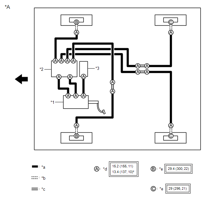
| *A | for HV Model | - | - |
| *1 | Brake Booster with Master Cylinder Assembly | *2 | Brake Actuator Assembly |
| *3 | Brake Booster Pump Assembly | - | - |
| *a | Brake Line | *b | Flexible Hose |
| *c | Brake Tube Way | *d | Union Nut |
| *e | Union Bolt | - | - |
.png) | Tightening torque for "Major areas involving basic vehicle performance such as moving/turning/stopping": N*m (kgf*cm, ft.*lbf) | * | For use with a union nut wrench |
.png) | Front | - | - |
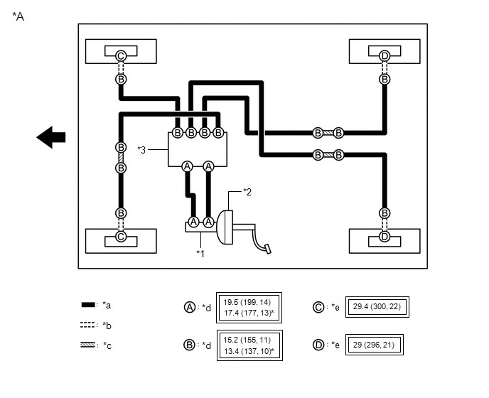
| *A | for Gasoline Model | - | - |
| *1 | Brake Master Cylinder Sub-assembly | *2 | Brake Booster Assembly |
| *3 | Brake Actuator Assembly | - | - |
| *a | Brake Line | *b | Flexible Hose |
| *c | Brake Tube Way | *d | Union Nut |
| *e | Union Bolt | - | - |
| | Tightening torque for "Major areas involving basic vehicle performance such as moving/turning/stopping" : N*m (kgf*cm, ft.*lbf) | * | For use with a union nut wrench |
| | Front | - | - |
READ NEXT:
 Components
COMPONENTS ILLUSTRATION *1 BRAKE MASTER CYLINDER O-RING *2 BRAKE MASTER CYLINDER SUB-ASSEMBLY *3 BRAKE LINE *4 CONNECTOR *5 BRAKE BOOSTER ASSEMBLY - - Tightening t
Disassembly
DISASSEMBLY PROCEDURE 1. REMOVE BRAKE MASTER CYLINDER STRAIGHT PIN (a) Secure the brake master cylinder sub-assembly in a vise. NOTICE: Place aluminum plates on the vise to prevent damage to the brake
SEE MORE:
Power Mirror cannot be Adjusted with Power Mirror Switch
DESCRIPTION The outer mirror switch assembly sends the mirror adjust switch signals to the main body ECU (multiplex network body ECU). The main body ECU (multiplex network body ECU) then sends the received mirror adjust switch signals to each outer mirror control ECU assembly via CAN communication.
Headlight ECU LH Communication Stop Mode
DESCRIPTION Detection Item Symptom Trouble Area Headlight ECU LH Communication Stop Mode Any of the following conditions are met:
Communication stop for "HL AutoLeveling/AFS/AHS" is indicated on the "Communication Bus Check" screen of the Techstream.
Click here
Communication sto
