Lexus ES: Terminals Of Ecu
TERMINALS OF ECU
HINT:
Check from the rear of the connector while it is connected to the components.
RADIO RECEIVER ASSEMBLY
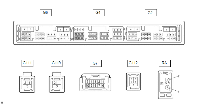
| Terminal No. (Symbol) | Wiring Color | Terminal Description | Condition | Specified Condition |
|---|---|---|---|---|
| G7-1 (FR+) - G6-1 (GND1) | W - W-B | Sound signal (Right) | Audio system playing | A waveform synchronized with sound signals is output |
| G7-2 (FL+) - G6-1 (GND1) | B - W-B | Sound signal (Left) | Audio system playing | A waveform synchronized with sound signals is output |
| G7-3 (RL+) - G6-1 (GND1) | B - W-B | Voice signal | Voice guidance sounding | A waveform synchronized with voice signals is output |
| G7-6 (FR-) - G6-1 (GND1) | R - W-B | Sound signal (Right) | Audio system playing | A waveform synchronized with sound signals is output |
| G7-7 (FL-) - G6-1 (GND1) | G - W-B | Sound signal (Left) | Audio system playing | A waveform synchronized with sound signals is output |
| G7-8 (RL-) - G6-1 (GND1) | W - W-B | Voice signal | Audio system playing | A waveform synchronized with sound signals is output |
| G6-1 (GND1) - Body ground | W-B - Body ground | Ground | Always | Below 1 Ω |
| G6-2 (GND2) - Body ground | LA-W - Body ground | Ground | Always | Below 1 Ω |
| G6-3 (+B) - G6-1 (GND1) | LA-B - W-B | Power source (+B) | Always | 11 to 14 V |
| G6-4 (+B1) - G6-1 (GND1) | R - W-B | Power source (+B) | Always | 11 to 14 V |
| G6-5 (TX1+) | B | AVC-LAN communication signal | - | - |
| G6-6 (TX1-) | W | AVC-LAN communication signal | - | - |
| G6-10 (AGND) - Body ground | Shielded - Body ground | Shield ground | Always | Below 1 Ω |
| G6-11 (VAL+) - G6-13 (VA-) | B - R | Sound signal (Left) | External device playing (When stereo jack used) | A waveform synchronized with sound signals is output |
| G6-12 (VAR+) - G6-13 (VA-) | W - R | Sound signal (Right) | External device playing (When stereo jack used) | A waveform synchronized with sound signals is output |
| G6-13 (VA-) - G6-1 (GND1) | R - W-B | Ground | Always | Below 1 V |
| G6-14 (ADPG) - G6-1 (GND1) | L - W-B | External device connection detection signal | External device connected | Below 1 V |
| External device not connected | 1.1 to 1.9 V | |||
| G6-15 (ACC1) - G6-1 (GND1) | GR - W-B | Power source (ACC) | Engine switch off | Below 1 V |
| Engine switch on (ACC) | 11 to 14 V | |||
| G6-16 (ACC) - G6-1 (GND1) | R - W-B | Power source (ACC) | Engine switch on (ACC) | 11 to 14 V |
| Engine switch off | Below 1 V | |||
| G6-17 (TX2+) | B | AVC-LAN communication signal | - | - |
| G6-18 (TX2-) | W | AVC-LAN communication signal | - | - |
| G6-21 (SW1) - G6-24 (SWG) | R - BR | Steering pad switch signal | No switch pushed | 2.97 to 3.56 V |
| Seek+ switch pushed | 0.27 to 0.35 V | |||
| Seek- switch pushed | 0.86 to 1.03 V | |||
| Volume+ switch pushed | 1.51 to 1.79 V | |||
| Volume- switch pushed | 2.22 to 2.66 V | |||
| G6-22 (SW2) - G6-24 (SWG) | G - BR | Steering pad switch signal | No switch pushed | 2.97 to 3.56 V |
| MODE switch pushed | 0.27 to 0.35 V | |||
| On/off hook switch pushed | 1.51 to 1.79 V | |||
| Voice switch pushed | 2.22 to 2.66 V | |||
| G6-24 (SWG) - Body ground | BR - Body ground | Steering pad switch ground | Always | Below 1 Ω |
| G6-25 (MUT1) - G6-1 (GND1) | G - W-B | Mute signal | Audio system playing | 2.0 V or higher |
| Audio system changing modes | Below 1 V | |||
| G6-27 (SPD) - G6-1 (GND1) | BE - W-B | Vehicle speed signal | See "Check Vehicle Signal" in Operation Check Click here | - |
| G4-1 (VMTF) - G6-1 (GND1) | G - W-B | Visual mute signal | Engine switch on (ACC) Screen display changing | 3.5 V or higher → Below 1 V → 3.5 V or higher |
| G4-5 (CNH1) | L | Local bus communication signal | - | - |
| G4-6 (CNL1) | W | Local bus communication signal | - | - |
| G4-13 (CANH) | B | CAN communication signal | - | - |
| G4-14 (CANL) | W | CAN communication signal | - | - |
| G4-15 (ILL+) - G6-1 (GND1) | G - W-B | Illumination signal | Light control switch off | Below 1 V |
| Light control switch in tail or head position | 11 to 14 V | |||
| G4-16 (ILL-) - G6-1 (GND1) | B - W-B | Illumination signal | Light control switch off | Below 1 V |
| Light control switch in tail or head position | Pulse generation | |||
| G4-19 (IG) - G6-1 (GND1) | SB - W-B | Power source (IG) | Engine switch off | Below 1 V |
| Engine switch on (IG) | 11 to 14 V | |||
| G4-21 (MIN+) - G6-1 (GND1) | P - W-B*1 W - W-B*2 | Microphone voice signal | See "Check Microphone" in Operation Check Click here | - |
| G4-22 (MIN-) - G6-1 (GND1) | L - W-B*1 R - W-B*2 | Microphone voice signal | See "Check Microphone" in Operation Check Click here | - |
| G4-23 (MACC) - G6-1 (GND1)*2 | B - W-B | Microphone power supply | Engine switch off | Below 1 V |
| Engine switch on (ACC) | 4 to 6 V | |||
| G4-24 (SGND) - Body ground | Shielded - Body ground | Shield ground | Always | Below 1 Ω |
| G4-25 (SNS2) - G6-1 (GND1) | W - W-B | Microphone connection detection signal | Always | Below 1 V |
| G112-1 (USV1) | - | Power source | - | - |
| G112-2 (US1-) | - | Data signal | - | - |
| G112-3 (US1+) | - | Data signal | - | - |
| G112-4 (UGD1) | - | Ground | - | - |
| G112-5 (USG1) | - | Shield ground | - | - |
| G119-1 (USB+)*1 | - | Data signal | - | - |
| G119-2 (USB-)*1 | - | Data signal | - | - |
| G119-3 (USBS)*1 | - | Ground | - | - |
| G111-1 (GVIF-) | - | Video signal (Digital) | - | - |
| G111-2 (GVIF+) | - | Video signal (Digital) | - | - |
| G111-3 (GND) | Shielded | Shield ground | - | - |
| G2-10 (USBV) - G2-11 (USBG)*1 | B - G | DCM (telematics transceiver) power supply | Engine switch off | Below 1 V |
| Engine switch on (ACC) | 4.75 to 5.25 V | |||
| G2-11 (USBG) - Body ground*1 | G | Ground | Always | Below 1 Ω |
| G2-12 (SGND) - Body ground*1 | Shielded - Body ground | Shield ground | Always | Below 1 Ω |
| RA-5 (ANT+) - G6-1 (GND1) | - - W-B | Power source of antenna | Engine switch on (ACC) Radio switch on and FM or AM selected | 11 to 14 V |
- *1: w/ Manual (SOS) Switch
- *2: w/o Manual (SOS) Switch
STEREO COMPONENT AMPLIFIER ASSEMBLY
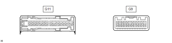
| Terminal No. (Symbol) | Wiring Color | Terminal Description | Condition | Specified Condition |
|---|---|---|---|---|
| G11-1 (+B) - G11-3 (GND)*1 | L - W-B | Power source (+B) | Always | 11 to 14 V |
| G11-2 (TMUT) - Body ground*2 | BE - Body ground | Mute signal | Engine switch on (ACC) Audio system playing | 2.0 V or higher |
| Emergency call mode | Below 1 V | |||
| G11-3 (GND) - Body ground | W-B - Body ground | Ground | Always | Below 1 Ω |
| G11-4 (WFL+) - G11-3 (GND) | LG - W-B | Sound signal (Front Left) | Audio system playing | A waveform synchronized with sound signals is output |
| G11-5 (WFR+) - G11-3 (GND) | R - W-B | Sound signal (Front Right) | Audio system playing | A waveform synchronized with sound signals is output |
| G11-6 (WF1+) - G11-3 (GND) | BE - W-B | Sound signal (Woofer) | Audio system playing | A waveform synchronized with sound signals is output |
| G11-7 (CTR+) - G11-3 (GND) | G - W-B | Sound signal (Front Center) | Audio system playing | A waveform synchronized with sound signals is output |
| G11-8 (RL+) - G11-3 (GND) | B - W-B | Sound signal (Rear Left) | Audio system playing | A waveform synchronized with sound signals is output |
| G11-9 (RR+) - G11-3 (GND) | P - W-B | Sound signal (Rear Right) | Audio system playing | A waveform synchronized with sound signals is output |
| G11-10 (TWL+) - G11-3 (GND)*1 | L - W-B | Sound signal (Front Left) | Audio system playing | A waveform synchronized with sound signals is output |
| G11-11 (TWR+) - G11-3 (GND)*1 | L - W-B | Sound signal (Front Right) | Audio system playing | A waveform synchronized with sound signals is output |
| G11-12 (FL+) - G11-3 (GND) | GR - W-B | Sound signal (Front Left) | Audio system playing | A waveform synchronized with sound signals is output |
| G11-13 (FR+) - G11-3 (GND) | B - W-B*2 P - W-B*3 | Sound signal (Front Right) | Audio system playing | A waveform synchronized with sound signals is output |
| G11-16 (+B2) - G11-3 (GND) | B - W-B | Power source (+B) | Always | 11 to 14 V |
| G11-17 (SPD) - G11-3 (GND) | GR - W-B | Vehicle speed signal | Engine switch on (IG) Wheel being rotated | Pulse generation |
| G11-18 (GND2) - Body ground | W-B - Body ground | Ground | Always | Below 1 Ω |
| G11-19 (WFL-) - G11-3 (GND) | P - W-B | Sound signal (Front Left) | Audio system playing | A waveform synchronized with sound signals is output |
| G11-20 (WFR-) - G11-3 (GND) | SB - W-B | Sound signal (Front Right) | Audio system playing | A waveform synchronized with sound signals is output |
| G11-21 (WF1-) - G11-3 (GND) | L - W-B | Sound signal (Woofer) | Audio system playing | A waveform synchronized with sound signals is output |
| G11-22 (CTR-) - G11-3 (GND) | W - W-B | Sound signal (Front Center) | Audio system playing | A waveform synchronized with sound signals is output |
| G11-23 (RL-) - G11-3 (GND) | Y - W-B | Sound signal (Rear Left) | Audio system playing | A waveform synchronized with sound signals is output |
| G11-24 (RR-) - G11-3 (GND) | W - W-B | Sound signal (Rear Right) | Audio system playing | A waveform synchronized with sound signals is output |
| G11-25 (TWL-) - G11-3 (GND)*1 | W - W-B | Sound signal (Front Left) | Audio system playing | A waveform synchronized with sound signals is output |
| G11-26 (TWR-) - G11-3 (GND)*1 | R - W-B | Sound signal (Front Right) | Audio system playing | A waveform synchronized with sound signals is output |
| G11-27 (FL-) - G11-3 (GND) | W - W-B | Sound signal (Front Left) | Audio system playing | A waveform synchronized with sound signals is output |
| G11-28 (FR-) - G11-3 (GND) | W - W-B*2 V - W-B*3 | Sound signal (Front Right) | Audio system playing | A waveform synchronized with sound signals is output |
| G9-1 (MUTE) - G11-3 (GND) | G - W-B | Mute signal | Engine switch on (ACC) Audio system playing | 2.0 V or higher |
| Audio system changing modes | Below 1 V | |||
| G9-2 (L-) - G11-3 (GND) | G - W-B | Sound signal (Left) | Audio system playing | A waveform synchronized with sound signals is output |
| G9-3 (L+) - G11-3 (GND) | B - W-B | Sound signal (Left) | Audio system playing | A waveform synchronized with sound signals is output |
| G9-4 (R-) - G11-3 (GND) | R - W-B | Sound signal (Right) | Audio system playing | A waveform synchronized with sound signals is output |
| G9-5 (R+) - G11-3 (GND) | W - W-B | Sound signal (Right) | Audio system playing | A waveform synchronized with sound signals is output |
| G9-6 (SLD) - Body ground | Shielded - Body ground | Shield ground | Always | Below 1 Ω |
| G9-7 (TX-) | W | AVC-LAN communication signal | - | - |
| G9-8 (TX+) | B | AVC-LAN communication signal | - | - |
| G9-12 (ACC) - G11-3 (GND) | W - W-B | Power source (ACC) | Engine switch off | Below 1 V |
| Engine switch on (ACC) | 11 to 14 V | |||
| G9-14 (II1-) - G11-3 (GND) | W - W-B | Voice signal | Voice guidance sounding | A waveform synchronized with voice signals is output |
| G9-15 (II1+) - G11-3 (GND) | B - W-B | Voice signal | Voice guidance sounding | A waveform synchronized with voice signals is output |
| G9-18 (SLD1) - Body ground | Shielded - Body ground | Shield ground | Always | Below 1 Ω |
- *1: for 17 Speakers
- *2: w/ Manual (SOS) Switch
- *3: w/o Manual (SOS) Switch
MULTI-DISPLAY ASSEMBLY
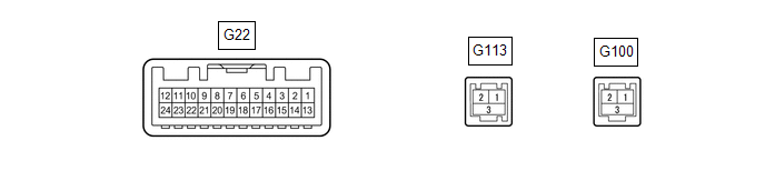
| Terminal No. (Symbol) | Wiring Color | Terminal Description | Condition | Specified Condition |
|---|---|---|---|---|
| G22-2 (ILL) - G22-13 (GND1) | LA-R - LA | Illumination signal | Light control switch off | Below 1 V |
| Light control switch in tail or head position | 11 to 14 V | |||
| G22-6 (TX1+) | B | AVC-LAN communication signal | - | - |
| G22-7 (TX+) | B | AVC-LAN communication signal | - | - |
| G22-8 (V+) - G22-13 (GND1)*1 | B - LA | Video signal | Engine switch on (IG) Shift lever in R Camera lens not covered, displaying image | Pulse generation (Refer to waveform 1) |
| Engine switch on (IG) Shift lever in R Camera lens covered, blacking out screen | Pulse generation (Refer to waveform 2) | |||
| G22-9 (V-) - G22-13 (GND1)*1 | W - LA | Ground | Always | Below 1 V |
| G22-10 (CA+) - G22-21(CGND)*1 | R - G | Rear television camera assembly power supply | Engine switch on (ACC) | 5.5 to 7.05 V |
| G22-11 (VMTI) - G22-13 (GND1) | G - LA | Visual mute signal | When image on display switches | 3.5 V or higher → Below 1 V → 3.5 V or higher |
| G22-12 (B) - G22-13 (GND1) | R - LA | Power source (+B) | Always | 11 to 14 V |
| G22-13 (GND1) - Body ground | LA - Body ground | Ground | Always | Below 1 Ω |
| G22-18 (TX1-) | W | AVC-LAN communication signal | - | - |
| G22-19 (TX-) | W | AVC-LAN communication signal | - | - |
| G22-20 (CSLD) - Body ground*1 | Shielded - Body ground | Shield ground | Always | Below 1 Ω |
| G22-21 (CGND) - Body ground*1 | G - Body ground | Camera ground | Always | Below 1 Ω |
| G22-24 (ACC) - G22-13 (GND1) | GR - LA | Power source (ACC) | Engine switch off | Below 1 V |
| Engine switch on (ACC) | 11 to 14 V | |||
| G113-1 (GVIF+) | - | Video signal (Digital) | - | - |
| G113-2 (GVIF-) | - | Video signal (Digital) | - | - |
| G113-3 (GND) | Shielded | Shield ground | - | - |
| G100-1 (GV+)*2 | - | Video signal (Digital) | - | - |
| G100-2 (GV-)*2 | - | Video signal (Digital) | - | - |
| G100-3 (GND)*2 | Shielded | Shield ground | - | - |
- *1: w/ Parking Assist Monitor System
- *2: w/ Panoramic View Monitor System
(a) Reference (Oscilloscope waveform):
(w/ Parking Assist Monitor System)
(1) Waveform 1 (camera lens not covered, displaying an image)
| Item | Content |
|---|---|
| Measurement terminal | G22-8 (V+) - G22-13 (GND1) |
| Measurement setting | 200 mV/DIV., 50 μs/DIV. |
| Condition | Engine switch on (IG), shift lever in R |
HINT:
- The video waveform changes according to the image sent by the rear television camera assembly.
- The video waveform is constantly output when the engine switch is on (ACC).
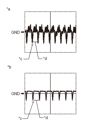
| *a | Waveform 1 (camera lens is not covered, displaying an image) |
| *b | Waveform 2 (camera lens is covered, blacking out the screen) |
| *c | Synchronization Signal |
| *d | Video Waveform |
(2) Waveform 2 (camera lens covered, blacking out the screen)
| Item | Content |
|---|---|
| Measurement terminal | G22-8 (V+) - G22-13 (GND1) |
| Measurement setting | 200 mV/DIV., 50 μs/DIV. |
| Condition | Engine switch on (IG), shift lever in R |
HINT:
- The video waveform changes according to the image sent by the rear television camera assembly.
- The video waveform is constantly output when the engine switch is on (ACC).
REMOTE TOUCH (REMOTE OPERATION CONTROLLER ASSEMBLY)

| Terminal No. (Symbol) | Wiring Color | Terminal Description | Condition | Specified Condition |
|---|---|---|---|---|
| G56-1 (+B) - G56-10 (GND) | R - LA | Power source (+B) | Always | 11 to 14 V |
| G56-2 (ILL+) - G56-10 (GND) | SB - LA | Illumination signal | Light control switch off | Below 1 V |
| Light control switch in tail or head position | 11 to 14 V | |||
| G56-5 (ILL-) - G56-10 (GND) | GR - LA | Illumination signal | Light control switch off | Below 1 V |
| Light control switch in tail or head position | Pulse generation | |||
| G56-6 (ACC) - G56-10 (GND) | P - LA | Power source (ACC) | Engine switch off | Below 1 V |
| Engine switch on (ACC) | 11 to 14 V | |||
| G56-8 (MO-) | W | Local bus communication signal | - | - |
| G56-9 (MO+) | B | Local bus communication signal | - | - |
| G56-10 (GND) - Body ground | LA - Body ground | Ground | Always | Below 1 Ω |
CLOCK ASSEMBLY

| Terminal No. (Symbol) | Wiring Color | Terminal Description | Condition | Specified Condition |
|---|---|---|---|---|
| G44-1 (B) - G44-7 (E) | LA-L - W-B | Power source (+B) | Always | 11 to 14 V |
| G44-2 (ACC) - G44-7 (E) | R - W-B | Power source (ACC) | Engine switch off | Below 1 V |
| Engine switch on (ACC) | 11 to 14 V | |||
| G44-5 (TX+1) | P | Local bus communication signal | - | - |
| G44-6 (TX-1) | W | Local bus communication signal | - | - |
| G44-7 (E) - Body ground | W-B - Body ground | Ground | Always | Below 1 V |
AIR CONDITIONING CONTROL ASSEMBLY

| Terminal No. (Symbol) | Wiring Color | Terminal Description | Condition | Specified Condition |
|---|---|---|---|---|
| G23-1 (TX1+) | B | AVC-LAN communication signal | - | - |
| G23-2 (TX1-) | W | AVC-LAN communication signal | - | - |
| G23-4 (E) - Body ground | W-B - Body ground | Ground | Always | Below 1 V |
| G23-7 (ACC) - G23-4 (E) | P - W-B | Power source (ACC) | Engine switch off | Below 1 V |
| Engine switch on (ACC) | 11 to 14 V | |||
| G23-8 (IG+) - G23-4 (E) | R - W-B | Power source (IG) | Engine switch on (IG) | 11 to 14 V |
| Engine switch off | Below 1 V | |||
| G23-16 (+B) - G23-4 (E) | GR - W-B | Power source (+B) | Always | 11 to 14 V |
DCM (TELEMATICS TRANSCEIVER) (w/ Manual (SOS) Switch)
Click here .gif)
COMBINATION METER ASSEMBLY
Click here
PARKING ASSIST ECU (w/ Panoramic View Monitor System)
Click here
REAR TELEVISION CAMERA ASSEMBLY (w/ Parking Assist Monitor System)
Click here
READ NEXT:
 Sending Malfunction (Navigation to APGS) (U0073,U0100,U0129,U0140,U0155,U0164,U0198,U023B,U0265,U1110)
DESCRIPTION These DTCs are stored when a malfunction occurs in the CAN communication circuit. DTC No. Detection Item DTC Detection Condition Trouble Area U0073 Sending Malfunction (Navi
USB Audio System Recognition/Play Error
DESCRIPTION When a USB device or "iPod" is connected to the USB jack of the No. 1 stereo jack adapter assembly, it must have playable files. The device must also communicate with and be recognized by
Vehicle Speed Signal Circuit between Stereo Component Amplifier and Combination Meter
DESCRIPTION The stereo component amplifier assembly receives a vehicle speed signal from the combination meter assembly to control the ASL function. HINT:
A voltage of 12 V or 5 V is output from ea
SEE MORE:
Diagnosis System
DIAGNOSIS SYSTEM DESCRIPTION (a) The DCM (telematics transceiver) control the vehicle safety connect system functions. Safety connect system data and Diagnostic Trouble Codes (DTCs) can be read through the vehicle Data Link Connector 3 (DLC3). In some cases, a malfunction may be occurring in the saf
Components
COMPONENTS ILLUSTRATION *A for A25A-FXS *B for 2GR-FKS *1 REAR FLOOR SIDE MEMBER COVER *2 REAR NO. 1 FLOOR BOARD *3 SUSPENSION TOWER DAMPER - - N*m (kgf*cm, ft.*lbf): Specified torque * For use with a union nut wrench
