Lexus ES: System Diagram
Lexus ES (XZ10) Service Manual / Drivetrain / Gf1a (transfer / 4wd / Awd) / Dynamic Torque Control Awd System / System Diagram
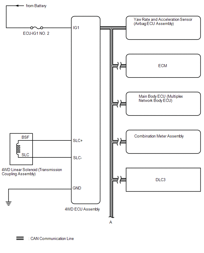
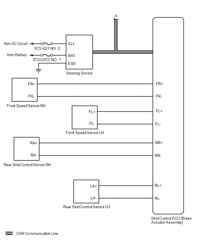
SYSTEM DIAGRAM
READ NEXT:
 Terminals Of Ecu
TERMINALS OF ECU CHECK 4WD ECU ASSEMBLY (a) Measure the voltage and resistance of the connector. Terminal No. (Symbol) Wiring Color Terminal Description Condition Specified Condition G
Control Module Communication Bus Off (U0073,U0100,U0126,U0129)
DESCRIPTION The 4WD ECU assembly inputs the signals sent from the ECM, skid control ECU (brake actuator assembly) and steering sensor via CAN communication. When DTCs indicating a CAN communication sy
SEE MORE:
Components
COMPONENTS ILLUSTRATION *A for Driver Side *B for Front Passenger Side *1 COURTESY LIGHT ASSEMBLY *2 FRONT DOOR TRIM BOARD SUB-ASSEMBLY *3 MULTIPLEX NETWORK MASTER SWITCH ASSEMBLY WITH FRONT DOOR UPPER ARMREST BASE PANEL *4 NO. 2 DOOR TRIM PAD *5 OUTER MIRROR CONT
Reassembly
REASSEMBLY PROCEDURE 1. INSTALL SPARK PLUG TUBE HINT: When using a new cylinder head sub-assembly, the spark plug tubes must be replaced. (a) Apply adhesive to a new spark plug tube as shown in the illustration. Adhesive: Toyota Genuine Adhesive 1324, Three Bond 1324 or equivalent Standard Appli
© 2016-2026 Copyright www.lexguide.net
