Lexus ES: Terminals Of Ecu
TERMINALS OF ECU
CHECK 4WD ECU ASSEMBLY
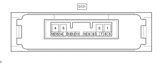
(a) Measure the voltage and resistance of the connector.
| Terminal No. (Symbol) | Wiring Color | Terminal Description | Condition | Specified Condition |
|---|---|---|---|---|
| G131-6 (CANH) - G131-5 (CANL) | G - W | HIGH-level CAN bus wire - LOW-level CAN bus wire | Cable disconnected from negative (-) battery terminal | 54 to 69 Ω |
| G131-4 (GND) - Body ground | W-B - Body ground | Ground | Always | Below 1 Ω |
| G131-3 (IG1) - G131-4 (GND) | BE - W-B | Power source voltage | Engine switch on (IG) | 11 to 14 V |
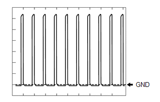
| G131-2 (SLC+) - G131-1 (SLC-) | W - B | 4WD linear solenoid signal | D position, engine idling | Pulse generation (See waveform 1) |
If the result is not as specified, the 4WD ECU assembly may have a malfunction.
(b) Using an oscilloscope, check the waveform 1.
Waveform 1 (Reference)| Item | Content |
|---|---|
| Terminal No. (Symbol) | G131-2 (SLC+) - G131-1 (SLC-) |
| Tester Range | 2 V/DIV., 1 msec./DIV. |
| Condition | D position, engine idling |
READ NEXT:
 Control Module Communication Bus Off (U0073,U0100,U0126,U0129)
DESCRIPTION The 4WD ECU assembly inputs the signals sent from the ECM, skid control ECU (brake actuator assembly) and steering sensor via CAN communication. When DTCs indicating a CAN communication sy
Components
COMPONENTS ILLUSTRATION *1 PROPELLER SHAFT HEAT INSULATOR *2 NO. 1 PROPELLER SHAFT HEAT INSULATOR BRACKET SUB-ASSEMBLY *3 REAR ENGINE MOUNTING BRACKET SUB-ASSEMBLY *4 TRANSFER ASSE
SEE MORE:
Cornering Light Circuit
DESCRIPTION The headlight ECU sub-assembly controls the cornering lights. WIRING DIAGRAM except Bulb Type Turn Signal Light (for TMMK Made) for Bulb Type Turn Signal Light (for TMMK Made) CAUTION / NOTICE / HINT NOTICE:
If the headlight ECU sub-assembly LH has been replaced, it is necessary to
Excessive Brake Pedal Travel (No Fluid Leaks and No Air in System)
CAUTION / NOTICE / HINT NOTICE: After replacing the skid control ECU (brake actuator assembly), perform acceleration sensor zero point calibration and store system information memorization. Click here PROCEDURE 1. PRE-INSPECTION (a) Brake pedal inspection (1) Perform a visual inspection a
