Lexus ES: Disassembly
DISASSEMBLY
PROCEDURE
1. REMOVE KICK DOOR CONTROL SENSOR WITH BRACKET (w/ Hands Free Power Trunk Lid)
Click here .gif)
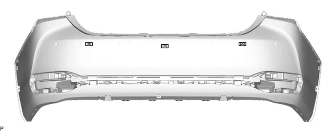
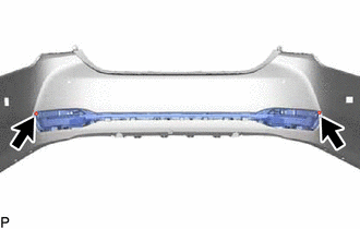
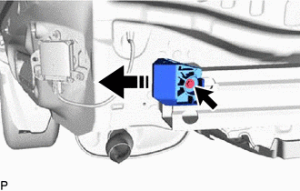
2. REMOVE REAR CENTER ULTRASONIC SENSOR (w/ Parking Support Alert System)
Click here
HINT:
Use the same procedure for the RH side and LH side.
3. REMOVE REAR CORNER ULTRASONIC SENSOR (w/ Parking Support Alert System)
Click here
HINT:
Use the same procedure for the RH side and LH side.
4. REMOVE REAR CENTER ULTRASONIC SENSOR RETAINER (w/ Parking Support Alert System)
Click here
HINT:
Use the same procedure for the RH side and LH side.
5. REMOVE REAR CORNER ULTRASONIC SENSOR RETAINER (w/ Parking Support Alert System)
Click here
HINT:
Use the same procedure for the RH side and LH side.
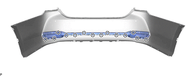
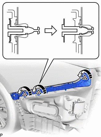
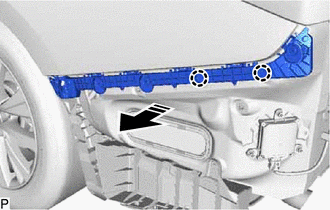
6. REMOVE NO. 2 LUGGAGE ROOM WIRE (w/ Wire Harness)
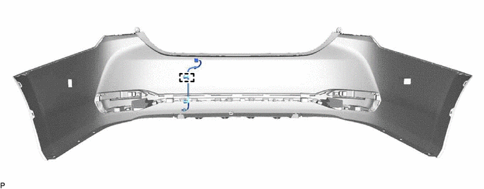
(a) w/ Hands Free Power Trunk Lid without Parking Support Alert System:
(1) Disengage the clamp to remove the No. 2 luggage room wire.
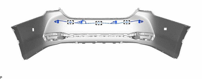
(b) w/ Parking Support Alert System without Hands Free Power Trunk Lid:
(1) Disengage the 3 clamps to remove the No. 2 luggage room wire.
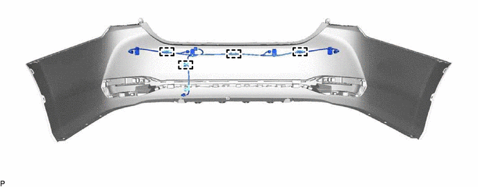
(c) w/ Hands Free Power Trunk Lid and Parking Support Alert System:
(1) Disengage the 4 clamps to remove the No. 2 luggage room wire.
7. REMOVE ULTRASONIC SENSOR CLIP (w/ Wire Harness)
(a) w/ Hands Free Power Trunk Lid without Parking Support Alert System:
(1) Remove the ultrasonic sensor clip.
(b) w/ Parking Support Alert System without Hands Free Power Trunk Lid:
(1) Remove the 3 ultrasonic sensor clips.
(c) w/ Hands Free Power Trunk Lid and Parking Support Alert System:
(1) Remove the 4 ultrasonic sensor clips.

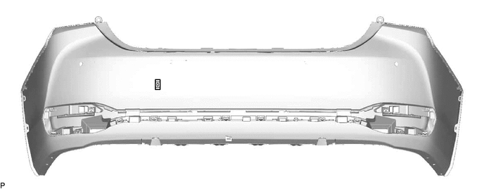
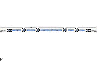
8. REMOVE NO. 1 MOULDING TAPE
| (a) Remove the No. 1 moulding tape. HINT: Use the same procedure for the RH side and LH side. |
|
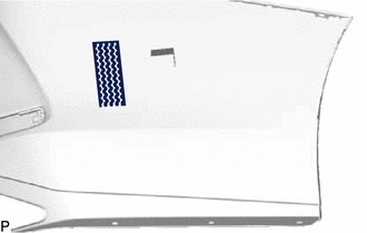
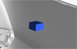
9. REMOVE REAR BUMPER PAD LH
| (a) Remove the rear bumper pad LH. |
|
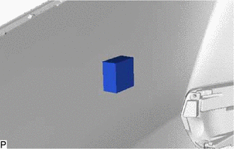
10. REMOVE REAR BUMPER PAD RH
| (a) Remove the rear bumper pad RH. |
|
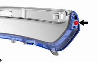
11. REMOVE REFLEX REFLECTOR ASSEMBLY
| (a) Remove the 2 screws. |
|
(b) Disengage the 14 claws.
| (c) Remove the screw. HINT: Use the same procedure for the RH side and LH side. |
|
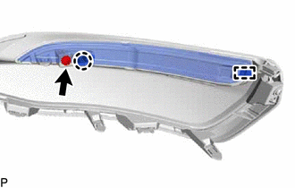
(d) Disengage the claw and guide to remove the reflex reflector assembly.
HINT:
Use the same procedure for the RH side and LH side.
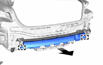
12. REMOVE REAR CENTER BUMPER SUB-ASSEMBLY
13. REMOVE REAR BUMPER BAR
| (a) Remove the 3 screws. |
|
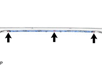
| (b) Disengage the 4 claws and 2 guides to remove the rear bumper bar. |
|
14. REMOVE REAR BUMPER BAR LH
| (a) Remove the screw. |
|
| (b) Disengage the 2 claws and guide to remove the rear bumper bar LH. |
|
15. REMOVE REAR BUMPER BAR RH
HINT:
Use the same procedure as for the LH side.
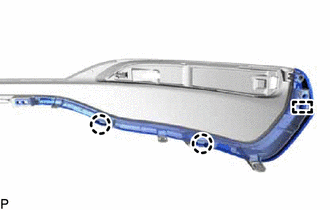
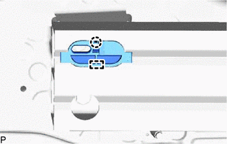
16. REMOVE NO. 2 REAR BUMPER SIDE SUPPORT LH
(a) Disengage the 3 clips as shown in the illustration.
.png) | Remove in this Direction |
(b) Disengage the 2 claws to remove the No. 2 rear bumper side support LH as shown in the illustration.
| | Remove in this Direction |
17. REMOVE NO. 2 REAR BUMPER SIDE SUPPORT RH
HINT:
Use the same procedure as for the LH side.
18. REMOVE LUGGAGE COMPARTMENT FLOOR MAT
Click here
19. REMOVE SPARE WHEEL COVER TRAY
Click here
20. REMOVE REAR FLOOR FINISH PLATE
Click here
21. REMOVE LUGGAGE COMPARTMENT TRIM COVER RH
Click here
22. REMOVE LUGGAGE COMPARTMENT TRIM COVER LH
Click here
23. REMOVE LUGGAGE COMPARTMENT TRIM INNER COVER RH
Click here
24. REMOVE LUGGAGE COMPARTMENT TRIM INNER COVER LH
Click here
25. REMOVE REAR COMBINATION LIGHT LENS AND BODY LH
Click here
26. REMOVE REAR COMBINATION LIGHT LENS AND BODY RH
HINT:
Use the same procedure as for the LH side.
27. REMOVE REAR BUMPER UPPER RETAINER LH
| (a) Remove the screw and rear bumper upper retainer LH. |
|
28. REMOVE REAR BUMPER UPPER RETAINER RH
HINT:
Use the same procedure as for the LH side.
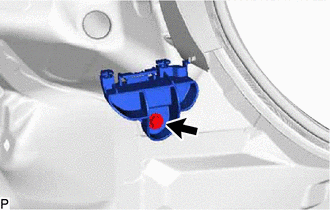
29. REMOVE LOWER REAR BUMPER SIDE RETAINER LH
| (a) Remove the screw. |
|
.png)
(b) Disengage the 2 clips to remove the lower rear bumper side retainer LH.
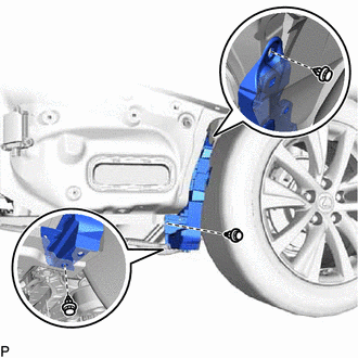
30. REMOVE REAR BUMPER SIDE SUPPORT LH
| (a) Remove the 2 grommets. |
|
.png)
| (b) Remove the 2 clips and rear bumper side support LH. |
|
.png)
31. REMOVE REAR BUMPER SIDE SUPPORT RH
| (a) Remove the 2 grommets. |
|
| (b) Remove the 3 clips and rear bumper side support RH. |
|
32. REMOVE REAR BUMPER ENERGY ABSORBER
(a) Disengage the 2 guides to remove the rear bumper energy absorber as shown in the illustration.
| | Remove in this Direction |
33. REMOVE REAR BUMPER PROTECTOR LH
(a) Remove the screw and rear bumper protector LH as shown in the illustration.
| | Remove in this Direction |
34. REMOVE REAR BUMPER PROTECTOR RH
HINT:
Use the same procedure as for the LH side.
35. REMOVE REAR BUMPER PROTECTOR INSERT LH
| (a) Disengage the claw and guide to remove the rear bumper protector insert LH. |
|
36. REMOVE REAR BUMPER PROTECTOR INSERT RH
HINT:
Use the same procedure as for the LH side.
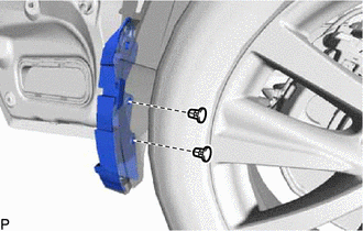
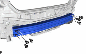
37. REMOVE REAR BUMPER REINFORCEMENT
| (a) Remove the 6 bolts and rear bumper reinforcement. |
|
READ NEXT:
 Reassembly
REASSEMBLY PROCEDURE 1. INSTALL REAR BUMPER REINFORCEMENT (a) Install the rear bumper reinforcement with the 6 bolts. Torque: 35 N·m {357 kgf·cm, 26 ft·lbf} 2. INSTALL REAR BUMPER P
Installation
INSTALLATION PROCEDURE 1. INSTALL REAR BUMPER ASSEMBLY (a) w/ Wire Harness: (1) Connect the connector. (b) Engage the 6 claws as shown in the illustration. Install in this Direction (c) Enga
SEE MORE:
Terminals Of Ecu
TERMINALS OF ECU CHECK WINDSHIELD WIPER MOTOR ASSEMBLY (a) Disconnect the A38 windshield wiper motor assembly connector. (b) Measure the voltage and resistance on the wire harness side connector according to the value(s) in the table below. Terminal No. (Symbol) Wiring Color Terminal Descrip
Brake Fluid (for Gasoline Model)
Components
COMPONENTS
ILLUSTRATION
*1
BRAKE MASTER CYLINDER RESERVOIR FILLER CAP ASSEMBLY
-
-
ILLUSTRATION
*1
FRONT DISC BRAKE BLEEDER PLUG
*2
FRONT DISC BRAKE BLEEDER PLUG CAP
