Lexus ES: System Diagram
SYSTEM DIAGRAM
| Transmitting ECU (Transmitter) | Receiving ECU | Signal | Communication Method |
|---|---|---|---|
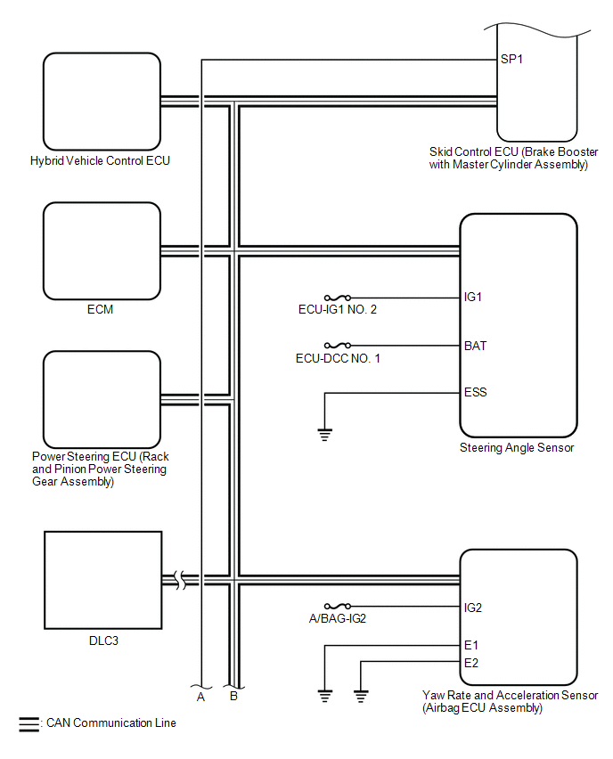
| Skid control ECU (Brake booster with master cylinder assembly) | Power steering ECU (Rack and pinion power steering gear assembly) |
| CAN communication line |
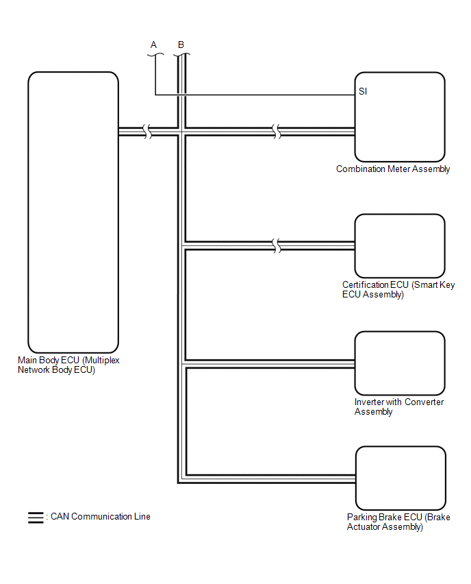
| Main body ECU (Multiplex network body ECU) | Skid control ECU (Brake booster with master cylinder assembly) | Driver side seat belt buckle switch signal | CAN communication line |
| Skid control ECU (Brake booster with master cylinder assembly) | Hybrid vehicle control ECU |
| CAN communication line |
| Hybrid vehicle control ECU | Skid control ECU (Brake booster with master cylinder assembly) |
| CAN communication line |
| Skid control ECU (Brake booster with master cylinder assembly) | Steering angle sensor | Steering angle sensor request signal | CAN communication line |
| Steering angle sensor | Skid control ECU (Brake booster with master cylinder assembly) | Steering angle sensor signal | CAN communication line |
| Skid control ECU (Brake booster with master cylinder assembly) | Yaw rate and acceleration sensor (Airbag ECU assembly) | Yaw rate and acceleration request signal | CAN communication line |
| Yaw rate and acceleration sensor (Airbag ECU assembly) | Skid control ECU (Brake booster with master cylinder assembly) | Yaw rate and acceleration signal | CAN communication line |
| Skid control ECU (Brake booster with master cylinder assembly) | Parking brake ECU (Brake actuator assembly) |
| CAN communication line |
| Parking brake ECU (Brake actuator assembly) | Skid control ECU (Brake booster with master cylinder assembly) |
| CAN communication line |
| Skid control ECU (Brake booster with master cylinder assembly) | Combination meter assembly |
| CAN communication line |
| Skid control ECU (Brake booster with master cylinder assembly) | Certification ECU (Smart key ECU assembly) |
| CAN communication line |
| Certification ECU (Smart key ECU assembly) | Skid control ECU (Brake booster with master cylinder assembly) | Push start switch signal | CAN communication line |
| Skid control ECU (Brake booster with master cylinder assembly) | Inverter with converter assembly |
| CAN communication line |
| Inverter with converter assembly | Skid control ECU (Brake booster with master cylinder assembly) |
| CAN communication line |
| Airbag ECU assembly | Skid control ECU (Brake booster with master cylinder assembly) | Secondary collision brake request signal | CAN communication line |
READ NEXT:
 Terminals Of Ecu
TERMINALS OF ECU TERMINALS OF ECU *a Component without harness connected (Skid Control ECU (Brake Booster with Master Cylinder Assembly)) - - Terminal No. (Symbol) Terminal Descripti
Test Mode Procedure
TEST MODE PROCEDURE WARNING LIGHT AND INDICATOR LIGHT INITIAL CHECK (a) When the power switch is turned on (IG), check that the ABS warning, brake warning / red (malfunction), brake warning / yellow (
TRAC does not Operate
DESCRIPTION When ABS, TRAC or VSC is operating, the skid control ECU (brake booster with master cylinder assembly) blinks the slip indicator light to inform the driver that slippage occurred. When in
SEE MORE:
Drive Motor "A" Position Sensor Signal Amplitude < (P0A3F21,P0A3F22)
DTC SUMMARY MALFUNCTION DESCRIPTION These DTCs indicate that the resolver output signal is abnormal. The cause of this malfunction may be one of the following: Area Main Malfunction Description Inverter low-voltage circuit The connectors are not connected properly Hybrid vehicle trans
Installation
INSTALLATION PROCEDURE 1. INSPECT AND ADJUST BRAKE BOOSTER PUSH ROD Click here 2. INSTALL BRAKE MASTER CYLINDER O-RING (a) Install a new brake master cylinder O-ring to the brake master cylinder sub-assembly. 3. INSTALL BRAKE MASTER CYLINDER SUB-ASSEMBLY NOTICE: When installing a new brake master
