Lexus ES: Inspection
INSPECTION
PROCEDURE
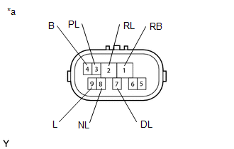
1. INSPECT PARK/NEUTRAL POSITION SWITCH ASSEMBLY
| (a) Measure the resistance according to the value(s) in the table below when the transmission control shaft lever is moved to each position. Standard Resistance:
If the result is not as specified, replace the park/neutral position switch assembly. |
|
READ NEXT:
 Installation
INSTALLATION PROCEDURE 1. INSTALL PARK/NEUTRAL POSITION SWITCH ASSEMBLY (a) Temporarily install the park/neutral position switch assembly to the automatic transaxle case sub-assembly with the 2 bolts.
On-vehicle Inspection
ON-VEHICLE INSPECTION PROCEDURE 1. SECURE VEHICLE (a) Fully apply the parking brake and chock a wheel. CAUTION:
Make sure to apply the parking brake and chock a wheel before performing this procedu
Removal
REMOVAL CAUTION / NOTICE / HINT The necessary procedures (adjustment, calibration, initialization or registration) that must be performed after parts are removed and installed, or replaced during park
SEE MORE:
PCU Interlock Circuit Open (P1CE213,P1CE292)
DTC SUMMARY MALFUNCTION DESCRIPTION The hybrid vehicle control ECU detects that a safety device (interlock) is operated or that there is an open circuit in the detection circuit. (Even if an open circuit occurs while the vehicle is stopped, the system determines that the safety device was operated.)
Air Conditioning Amplifier Communication Stop Mode
DESCRIPTION Detection Item Symptom Trouble Area Air Conditioning Amplifier Communication Stop Mode Any of the following conditions are met:
Communication stop for "Air Conditioning Amplifier" is indicated on the "Communication Bus Check" screen of the Techstream.
Click here
Comm
