Lexus ES: System Diagram
Lexus ES (XZ10) Service Manual / Audio & Visual & Telematics / Telematics / Telematics System (for Hv Model) / System Diagram
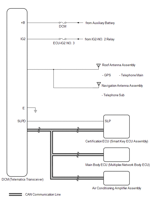
SYSTEM DIAGRAM
READ NEXT:
 Terminals Of Ecu
TERMINALS OF ECU HINT: Check from the rear of the connector while it is connected to the components. DCM (TELEMATICS TRANSCEIVER) Terminal No. (Symbol) Wiring Color Terminal Description Cond
Lost Communication with Body Control Module Missing Message (U014087,U015587,U016387)
DESCRIPTION These DTCs are stored when a malfunction occurs in the CAN communication circuit. DTC No. Detection Item DTC Detection Condition Trouble Area U014087 Lost Communication with
Utility
UTILITY CANCEL COMMUNICATION FUNCTION PAUSING HINT: This function is used to cancel communication function pausing mode. (a) Connect the Techstream to the DLC3. (b) Turn the power switch on (IG). (c)
SEE MORE:
Invalid Data Received from Hybrid Powertrain Control Module Invalid Serial Data Received (U059481)
DESCRIPTION If the hybrid vehicle control ECU cannot recognize the forward recognition camera. DTC U059481 is stored. DTC No. Detection Item DTC Detection Condition Trouble Area MIL DTC Output from U059481 Invalid Data Received from Hybrid Powertrain Control Module Invalid Serial
Removal
REMOVAL PROCEDURE 1. REMOVE RAIN SENSOR COVER *a Stopper Remove in this Direction (1) Remove in this Direction (2) (a) Release the stopper by pulling it out and disconnect the rain sensor as indicated by the arrows, in the order shown in the illustration. (b) Disengage the
© 2016-2026 Copyright www.lexguide.net
