Lexus ES: System Diagram
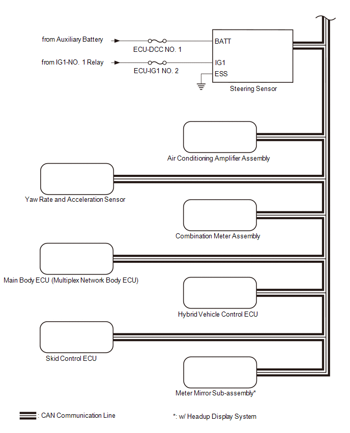
SYSTEM DIAGRAM
.png)
.png) w/ Blind Spot Monitor System
w/ Blind Spot Monitor System .png) w/ Panoramic View Monitor System
w/ Panoramic View Monitor System .png)
READ NEXT:
 Terminals Of Ecu
TERMINALS OF ECU CLEARANCE WARNING ECU ASSEMBLY (a) Disconnect the N41 clearance warning ECU assembly connector. (b) Measure the voltage and resistance on the wire harness side connector according to
Terminals Of Ecu
TERMINALS OF ECU CLEARANCE WARNING ECU ASSEMBLY (a) Disconnect the N41 clearance warning ECU assembly connector. (b) Measure the voltage and resistance on the wire harness side connector according to
Control Module Communication Bus "A" Off (U0073,U0100,U0124,U0126,U0129,U0140,U0155,U0164,U0265)
DESCRIPTION These DTCs are stored if there is a malfunction in the CAN communication system connected to the clearance warning ECU assembly. HINT: If CAN communication system DTCs are stored, they may
SEE MORE:
Diagnostic Trouble Code Chart
DIAGNOSTIC TROUBLE CODE CHART Blind Spot Monitor System DTC No. Detection Item Link C1A45 Vehicle Speed Sensor C1A45 Vehicle Speed Sensor C1A46 Yaw Rate Sensor C1A46 Yaw Rate Sensor C1A47 Steering Angle Sensor C1A47 Steering Angle S
Removal
REMOVAL CAUTION / NOTICE / HINT The necessary procedures (adjustment, calibration, initialization or registration) that must be performed after parts are removed and installed, or replaced during air fuel ratio sensor removal/installation are shown below. Necessary Procedures After Parts Removed/Ins
© 2016-2026 Copyright www.lexguide.net
