Lexus ES: Sub Radiator
Components
COMPONENTS
ILLUSTRATION
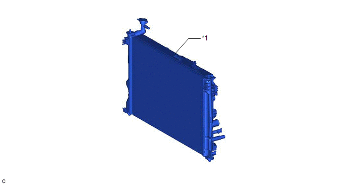
| *1 | RADIATOR ASSEMBLY | - | - |
Removal
REMOVAL
CAUTION / NOTICE / HINT
The necessary procedures (adjustment, calibration, initialization or registration) that must be performed after parts are removed and installed, or replaced during radiator assembly removal/installation are shown below.
Necessary Procedure After Parts Removed/Installed/Replaced| Replaced Part or Performed Procedure | Necessary Procedure | Effect/Inoperative Function when Necessary Procedure not Performed | Link |
|---|---|---|---|
| Front bumper assembly |
|
| |
| Front television camera view adjustment | Panoramic View Monitor System | for Initialization for Calibration | |
| Headlight ECU sub-assembly LH |
| Lighting system | |
| Change grille shutter control mode and/or perform initialization | Grille Shutter system | |
PROCEDURE
1. REMOVE RADIATOR ASSEMBLY
HINT:
The radiator (for inverter coolant) is part of the radiator (for Engine). If the radiator (for inverter coolant) needs to be replaced, replace the radiator assembly.
(a) Remove the radiator assembly.
Click here .gif)
Installation
INSTALLATION
PROCEDURE
1. INSTALL RADIATOR ASSEMBLY
HINT:
The radiator (for inverter coolant) is part of the radiator (for Engine). If the radiator (for inverter coolant) needs to be replaced, replace the radiator assembly.
(a) Install the radiator assembly.
Click here .gif)
READ NEXT:
 Components
COMPONENTS ILLUSTRATION *1 NO. 1 ENGINE UNDER COVER *2 FRONT WHEEL OPENING EXTENSION PAD LH *3 FRONT WHEEL OPENING EXTENSION PAD RH - - N*m (kgf*cm, ft.*lbf): Specified torq
Removal
REMOVAL PROCEDURE 1. REMOVE FRONT WHEEL OPENING EXTENSION PAD LH Click here 2. REMOVE FRONT WHEEL OPENING EXTENSION PAD RH Click here 3. REMOVE NO. 1 ENGINE UNDER COVER Click here 4. DRAIN
SEE MORE:
Components
COMPONENTS ILLUSTRATION *1 FORWARD RECOGNITION CAMERA *2 FORWARD RECOGNITION LATCH *3 NO. 1 FORWARD RECOGNITION COVER *4 NO. 2 FORWARD RECOGNITION COVER
Cooling Fan Circuit
DESCRIPTION The ECM calculates an appropriate cooling fan speed based on the engine coolant temperature, air conditioning switch status, refrigerant pressure, engine speed and vehicle speed, and sends a signal to the cooling fan ECU (fan with motor assembly). The cooling fan ECU (fan with motor asse
