Lexus ES: Stereo Component Amplifier
Components
COMPONENTS
ILLUSTRATION
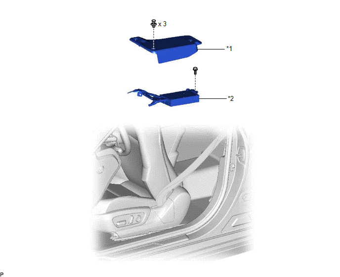
| *1 | AUDIO AMPLIFIER COVER | *2 | STEREO COMPONENT AMPLIFIER ASSEMBLY WITH BRACKET |
ILLUSTRATION
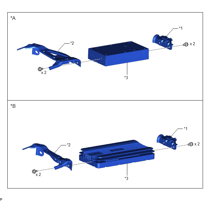
| *A | for 10 Speakers | *B | for 17 Speakers |
| *1 | NO. 1 AMPLIFIER BRACKET | *2 | NO. 2 AMPLIFIER BRACKET |
| *3 | STEREO COMPONENT AMPLIFIER ASSEMBLY | - | - |
Installation
INSTALLATION
PROCEDURE
1. INSTALL STEREO COMPONENT AMPLIFIER ASSEMBLY
2. INSTALL NO. 1 AMPLIFIER BRACKET
(a) Install the No. 1 amplifier bracket with the 2 screws.
3. INSTALL NO. 2 AMPLIFIER BRACKET
(a) Install the No. 2 amplifier bracket with the 2 screws.
4. INSTALL STEREO COMPONENT AMPLIFIER ASSEMBLY WITH BRACKET
(a) Operate the slide and vertical power seat switch knob and move the front seat assembly to the foremost position.
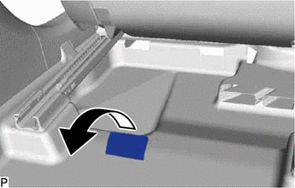
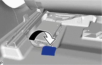
| (b) Turn back the front floor carpet assembly as shown in the illustration. |
|
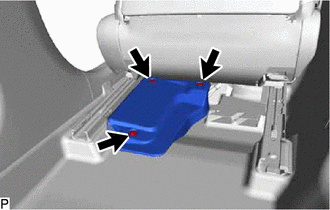
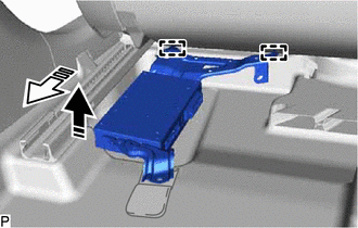
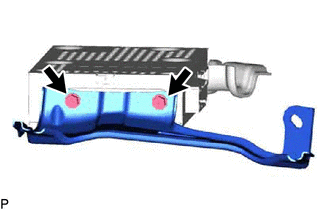
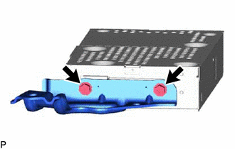
(c) Engage the 2 guides and temporarily install the stereo component amplifier assembly with bracket as shown in the illustration.
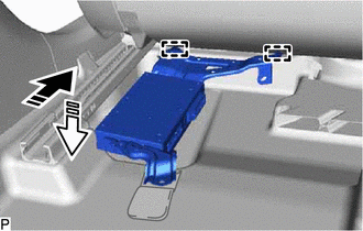
.png) | Install in this Direction (1) |
.png) | Install in this Direction (2) |
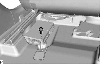
(d) Install the stereo component amplifier assembly with bracket with the bolt.
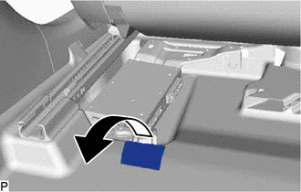
| (e) Return the front floor carpet assembly to its original position as shown in the illustration. |
|
(f) Engage the clamp.
(g) Connect each connector.
5. INSTALL AUDIO AMPLIFIER COVER
| (a) Install the audio amplifier cover with the 3 clips. HINT: Install the clips in the order shown in the illustration. |
|

Removal
REMOVAL
PROCEDURE
1. REMOVE AUDIO AMPLIFIER COVER
(a) Operate the slide and vertical power seat switch knob and move the front seat assembly to the foremost position.
| (b) Remove the 3 clips and audio amplifier cover. |
|
2. REMOVE STEREO COMPONENT AMPLIFIER ASSEMBLY WITH BRACKET
| (a) Disconnect each connector. |
|
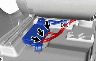
(b) Disengage the clamp.
| (c) Turn back the front floor carpet assembly as shown in the illustration. |
|
| (d) Remove the bolt. |
|
(e) Disengage the 2 guides and remove the stereo component amplifier assembly with bracket as shown in the illustration.
.png) | Remove in this Direction (1) |
.png) | Remove in this Direction (2) |
3. REMOVE NO. 2 AMPLIFIER BRACKET
| (a) Remove the 2 screws and No. 2 amplifier bracket. |
|
4. REMOVE NO. 1 AMPLIFIER BRACKET
| (a) Remove the 2 screws and No. 1 amplifier bracket. |
|
5. REMOVE STEREO COMPONENT AMPLIFIER ASSEMBLY
READ NEXT:
 Components
COMPONENTS ILLUSTRATION *1 CENTER INSTRUMENT CLUSTER FINISH PANEL SUB-ASSEMBLY *2 INSTRUMENT PANEL FINISH PANEL END LH *3 INSTRUMENT PANEL FINISH PANEL END RH *4 NO. 1 STEREO JACK
Installation
INSTALLATION PROCEDURE 1. INSTALL NO. 1 STEREO JACK ADAPTER ASSEMBLY (a) Engage the 2 claws to install the No. 1 stereo jack adapter assembly as shown in the illustration. Install in this Direc
SEE MORE:
Removal
REMOVAL CAUTION / NOTICE / HINT The necessary procedures (adjustment, calibration, initialization or registration) that must be performed after parts are removed and installed, or replaced during HV battery removal/installation are shown below. Necessary Procedures After Parts Removed/Installed/Repl
If your vehicle needs to be towed
If towing is necessary, we recommend
having your vehicle towed by
your Lexus dealer or commercial
towing service, using a wheel-lift
type truck or flatbed truck.
Use a safety chain system for all
towing, and abide by all state/provincial
and local laws.
WARNING
Observe the following preca
