Lexus ES: Components
COMPONENTS
ILLUSTRATION
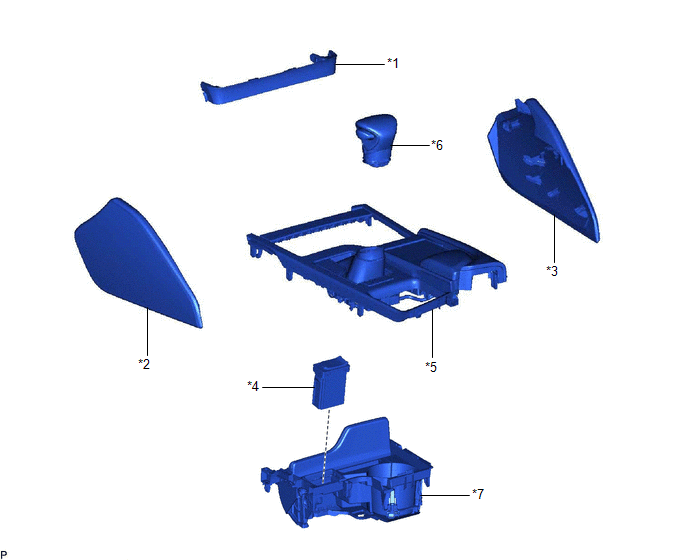
| *1 | CENTER INSTRUMENT CLUSTER FINISH PANEL SUB-ASSEMBLY | *2 | INSTRUMENT PANEL FINISH PANEL END LH |
| *3 | INSTRUMENT PANEL FINISH PANEL END RH | *4 | NO. 1 STEREO JACK ADAPTER ASSEMBLY |
| *5 | REAR UPPER CONSOLE PANEL SUB-ASSEMBLY | *6 | SHIFT LEVER KNOB SUB-ASSEMBLY |
| *7 | UPPER CONSOLE PANEL SUB-ASSEMBLY | - | - |
READ NEXT:
 Installation
INSTALLATION PROCEDURE 1. INSTALL NO. 1 STEREO JACK ADAPTER ASSEMBLY (a) Engage the 2 claws to install the No. 1 stereo jack adapter assembly as shown in the illustration. Install in this Direc
Installation
INSTALLATION PROCEDURE 1. INSTALL NO. 1 STEREO JACK ADAPTER ASSEMBLY (a) Engage the 2 claws to install the No. 1 stereo jack adapter assembly as shown in the illustration. Install in this Direc
Removal
REMOVAL PROCEDURE 1. REMOVE INSTRUMENT PANEL FINISH PANEL END LH Click here 2. REMOVE INSTRUMENT PANEL FINISH PANEL END RH Click here 3. REMOVE CENTER INSTRUMENT CLUSTER FINISH PANEL SUB-ASSEMBLY
SEE MORE:
Removal
REMOVAL CAUTION / NOTICE / HINT The necessary procedures (adjustment, calibration, initialization, or registration) that must be performed after parts are removed and installed, or replaced during propeller with center bearing shaft assembly removal/installation are shown below. Necessary Procedures
BSM Buzzer Malfunction (C2A5D)
DESCRIPTION This DTC is stored when the rear television camera assembly receives an RCTA buzzer circuit malfunction signal from the blind spot monitor sensor RH. DTC No. Detection Item DTC Detection Condition Trouble Area C2A5D BSM Buzzer Malfunction The RCTA buzzer circuit is abnor
© 2016-2026 Copyright www.lexguide.net
