Lexus ES: Installation
INSTALLATION
PROCEDURE
1. INSTALL NO. 1 STEREO JACK ADAPTER ASSEMBLY
(a) Engage the 2 claws to install the No. 1 stereo jack adapter assembly as shown in the illustration.
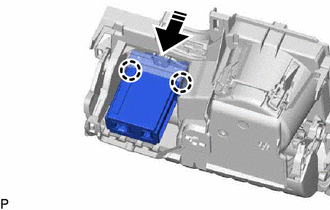
.png) | Install in this Direction |
2. INSTALL UPPER CONSOLE PANEL SUB-ASSEMBLY
Click here .gif)
3. INSTALL REAR UPPER CONSOLE PANEL SUB-ASSEMBLY
Click here
4. INSTALL SHIFT LEVER KNOB SUB-ASSEMBLY
for UA80E: Click here
for P710: Click here
5. INSTALL CENTER INSTRUMENT CLUSTER FINISH PANEL SUB-ASSEMBLY
Click here
6. INSTALL INSTRUMENT PANEL FINISH PANEL END RH
Click here
7. INSTALL INSTRUMENT PANEL FINISH PANEL END LH
Click here
READ NEXT:
 Installation
INSTALLATION PROCEDURE 1. INSTALL NO. 1 STEREO JACK ADAPTER ASSEMBLY (a) Engage the 2 claws to install the No. 1 stereo jack adapter assembly as shown in the illustration. Install in this Direc
Removal
REMOVAL PROCEDURE 1. REMOVE INSTRUMENT PANEL FINISH PANEL END LH Click here 2. REMOVE INSTRUMENT PANEL FINISH PANEL END RH Click here 3. REMOVE CENTER INSTRUMENT CLUSTER FINISH PANEL SUB-ASSEMBLY
Removal
REMOVAL PROCEDURE 1. REMOVE INSTRUMENT PANEL FINISH PANEL END LH Click here 2. REMOVE INSTRUMENT PANEL FINISH PANEL END RH Click here 3. REMOVE CENTER INSTRUMENT CLUSTER FINISH PANEL SUB-ASSEMBLY
SEE MORE:
Hybrid/EV Battery Control System Over Temperature (P30004B)
DESCRIPTION The hybrid vehicle control ECU monitors its internal operation and detects the following malfunction. DTC No. Detection Item DTC Detection Condition Trouble Area MIL Warning Indicate P30004B Hybrid/EV Battery Control System Over Temperature The HV battery temperature
Components
COMPONENTS ILLUSTRATION *A for Type A *B for Type B *1 FUEL PUMP GAUGE RETAINER *2 FUEL SUCTION TUBE WITH PUMP AND GAUGE ASSEMBLY *3 FUEL TANK MAIN TUBE SUB-ASSEMBLY *4 FUEL TANK PRESSURE SENSOR (VAPOR PRESSURE SENSOR) *5 FUEL TANK VENT HOSE SUB-ASSEMBLY *6 RE
© 2016-2026 Copyright www.lexguide.net
