Lexus ES: Sliding Roof does not Move by Operating Sliding Roof Control Switch
DESCRIPTION
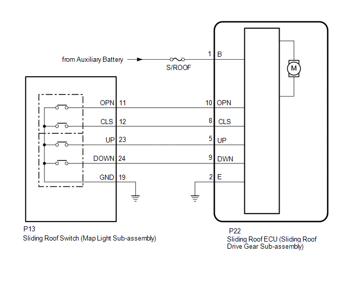
The sliding roof ECU (sliding roof drive gear sub-assembly) receives slide and tilt signals and operates its built-in motor when the sliding roof switch (map light sub-assembly) is operated.
WIRING DIAGRAM
CAUTION / NOTICE / HINT
NOTICE:
- Inspect the fuses for circuits related to this system before performing the following procedure.
-
If the sliding roof ECU (sliding roof drive gear sub-assembly) is removed and reinstalled or replaced, the sliding roof ECU (sliding roof drive gear sub-assembly) must be initialized.
Click here
.gif)
-
If a sliding roof ECU (sliding roof drive gear sub-assembly) DTC is output, first perform troubleshooting for the sliding roof ECU (sliding roof drive gear sub-assembly) DTC.
Click here
PROCEDURE
| 1. | PERFORM ACTIVE TEST USING TECHSTREAM (SLIDING ROOF) |
(a) Connect the Techstream to the DLC3.
(b) Turn the power switch on (IG).
(c) Turn the Techstream on.
(d) Enter the following menus: Body Electrical / Sliding Roof / Active Test.
(e) Perform the Active Test according to the display on the Techstream.
Body Electrical > Sliding Roof > Active Test| Tester Display | Measurement Item | Control Range | Diagnostic Note |
|---|---|---|---|
| Slide Roof | Operate sliding roof motor | OFF / Opn/Dwn / Clos/Up | - |
| Tester Display |
|---|
| Slide Roof |
OK:
Slide roof is operated using Techstream.
| NG | .gif) | GO TO STEP 5 |
|
.gif)
| 2. | READ VALUE USING TECHSTREAM |
(a) Enter the following menus: Body Electrical / Sliding Roof / Data List.
(b) Read the Data List according to the display on the Techstream.
Body Electrical > Sliding Roof > Data List| Tester Display | Measurement Item | Range | Normal Condition | Diagnostic Note |
|---|---|---|---|---|
| Open Switch | OPEN switch signal | OFF or ON | OFF: OPEN switch not pressed ON: OPEN switch pressed | - |
| Close Switch | CLOSE switch signal | OFF or ON | OFF: CLOSE switch not pressed ON: CLOSE switch pressed | - |
| Up Switch | UP switch signal | OFF or ON | OFF: UP switch not pressed ON: UP switch pressed | - |
| Down Switch | DOWN switch signal | OFF or ON | OFF: DOWN switch not pressed ON: DOWN switch pressed | - |
| Tester Display |
|---|
| Open Switch |
| Close Switch |
| Up Switch |
| Down Switch |
OK:
The Techstream display changes according to the operation of each switch as shown in the table.
| OK | | REPLACE SLIDING ROOF ECU (SLIDING ROOF DRIVE GEAR SUB-ASSEMBLY) |
|
| 3. | INSPECT SLIDING ROOF SWITCH (MAP LIGHT SUB-ASSEMBLY) |
(a) Remove the sliding roof switch (map light sub-assembly).
Click here
(b) Inspect the sliding roof switch (map light sub-assembly).
Click here
| NG | | REPLACE SLIDING ROOF SWITCH (MAP LIGHT SUB-ASSEMBLY) |
|
| 4. | CHECK HARNESS AND CONNECTOR (SLIDING ROOF ECU (SLIDING ROOF DRIVE GEAR SUB-ASSEMBLY) - SLIDING ROOF SWITCH (MAP LIGHT SUB-ASSEMBLY) AND BODY GROUND) |
(a) Disconnect the P13 sliding roof switch (map light sub-assembly) connector.
(b) Disconnect the P22 sliding roof ECU (sliding roof drive gear sub-assembly) connector.
(c) Measure the resistance according to the value(s) in the table below.
Standard Resistance:
| Tester Connection | Condition | Specified Condition |
|---|---|---|
| P22-8 (CLS) - P13-12 (CLS) | Always | Below 1 Ω |
| P22-8 (CLS) or P13-12 (CLS) - Body ground | Always | 10 kΩ or higher |
| P22-10 (OPN) - P13-11 (OPN) | Always | Below 1 Ω |
| P22-10 (OPN) or P13-11 (OPN) - Body ground | Always | 10 kΩ or higher |
| P22-9 (DWN) - P13-24 (DOWN) | Always | Below 1 Ω |
| P22-9 (DWN) or P13-24 (DOWN) - Body ground | Always | 10 kΩ or higher |
| P22-5 (UP) - P13-23 (UP) | Always | Below 1 Ω |
| P22-5 (UP) or P13-23 (UP) - Body ground | Always | 10 kΩ or higher |
| P13-19 (GND) - Body ground | Always | Below 1 Ω |
| P22-2 (E) - Body ground | Always | Below 1 Ω |
| OK | | REPLACE SLIDING ROOF ECU (SLIDING ROOF DRIVE GEAR SUB-ASSEMBLY) |
| NG | | REPAIR OR REPLACE HARNESS OR CONNECTOR |
| 5. | CHECK HARNESS AND CONNECTOR (SLIDING ROOF ECU (SLIDING ROOF DRIVE GEAR SUB-ASSEMBLY) - IG POWER SUPPLY AND BODY GROUND) |
| (a) Disconnect the P22 sliding roof ECU (sliding roof drive gear sub-assembly) connector. |
|
(b) Measure the voltage according to the value(s) in the table below.
Standard Voltage:
| Tester Connection | Condition | Specified Condition |
|---|---|---|
| P22-1 (B) - Body ground | Power switch off | 11 to 14 V |
(c) Measure the resistance according to the value(s) in the table below.
Standard Resistance:
| Tester Connection | Condition | Specified Condition |
|---|---|---|
| P22-2 (E) - Body ground | Always | Below 1 Ω |
| OK | | REPLACE SLIDING ROOF ECU (SLIDING ROOF DRIVE GEAR SUB-ASSEMBLY) |
| NG | | REPAIR OR REPLACE HARNESS OR CONNECTOR |
READ NEXT:
 Vehicle Approaching Speaker (for Front Side)
ComponentsCOMPONENTS ILLUSTRATION *1 COOL AIR INTAKE DUCT SEAL *2 VEHICLE APPROACHING SPEAKER ASSEMBLY N*m (kgf*cm, ft.*lbf): Specified torque - - RemovalREMOVAL PROCEDURE 1.
Vehicle Approaching Speaker Ecu
ComponentsCOMPONENTS ILLUSTRATION *1 VEHICLE APPROACHING SPEAKER CONTROLLER - - N*m (kgf*cm, ft.*lbf): Specified torque - - RemovalREMOVAL PROCEDURE 1. REMOVE RADIO RECEIVER
SEE MORE:
How To Proceed With Troubleshooting
CAUTION / NOTICE / HINT HINT:
Use the following procedure to troubleshoot the windshield deicer system.
*: Use the Techstream.
PROCEDURE 1. VEHICLE BROUGHT TO WORKSHOP
NEXT 2. CUSTOMER PROBLEM ANALYSIS HINT:
In troubleshooting, confirm that the problem s
Components
COMPONENTS ILLUSTRATION *A for Type A *B for Type B *1 FUEL PUMP GAUGE RETAINER *2 FUEL SUCTION TUBE WITH PUMP AND GAUGE ASSEMBLY *3 FUEL TANK MAIN TUBE SUB-ASSEMBLY *4 FUEL TANK PRESSURE SENSOR (VAPOR PRESSURE SENSOR) *5 FUEL TANK VENT HOSE SUB-ASSEMBLY *6 RE
