Lexus ES: Components
COMPONENTS
ILLUSTRATION
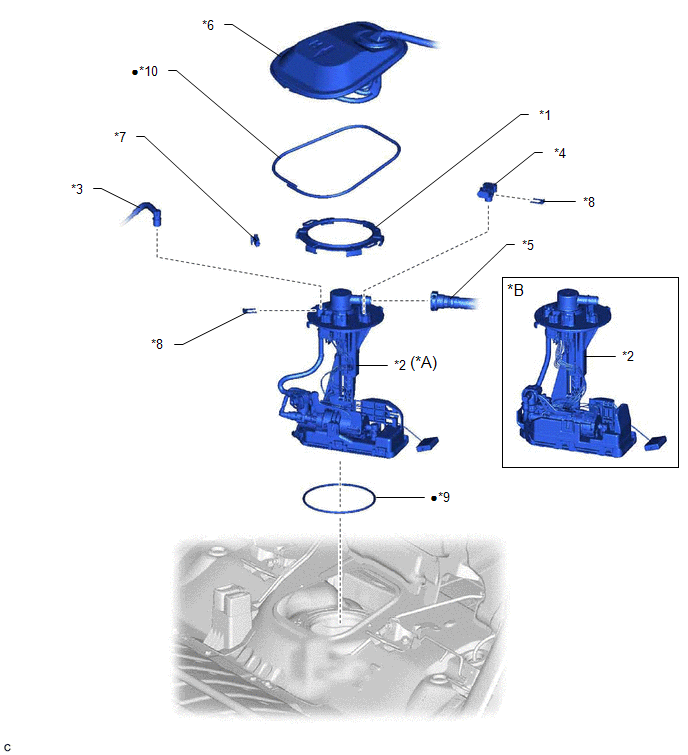
| *A | for Type A | *B | for Type B |
| *1 | FUEL PUMP GAUGE RETAINER | *2 | FUEL SUCTION TUBE WITH PUMP AND GAUGE ASSEMBLY |
| *3 | FUEL TANK MAIN TUBE SUB-ASSEMBLY | *4 | FUEL TANK PRESSURE SENSOR (VAPOR PRESSURE SENSOR) |
| *5 | FUEL TANK VENT HOSE SUB-ASSEMBLY | *6 | REAR FLOOR SERVICE HOLE COVER |
| *7 | NO. 1 FUEL TUBE CLAMP | *8 | TUBE JOINT CLIP |
| *9 | FUEL SUCTION TUBE SET GASKET | *10 | BUTYL TAPE |
| ● | Non-reusable part | - | - |
ILLUSTRATION
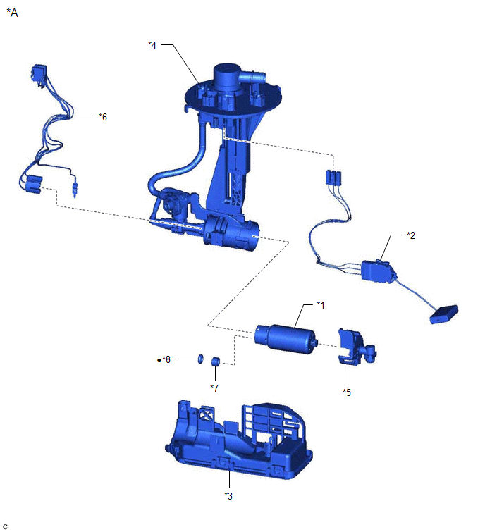
| *A | for Type A | - | - |
| *1 | FUEL PUMP | *2 | FUEL SENDER GAUGE ASSEMBLY |
| *3 | FUEL SUB-TANK SUB-ASSEMBLY | *4 | FUEL SUCTION PLATE SUB-ASSEMBLY |
| *5 | NO. 2 FUEL SUCTION SUPPORT | *6 | FUEL PUMP HARNESS |
| *7 | FUEL PUMP SPACER | *8 | O-RING |
| ● | Non-reusable part | - | - |
ILLUSTRATION
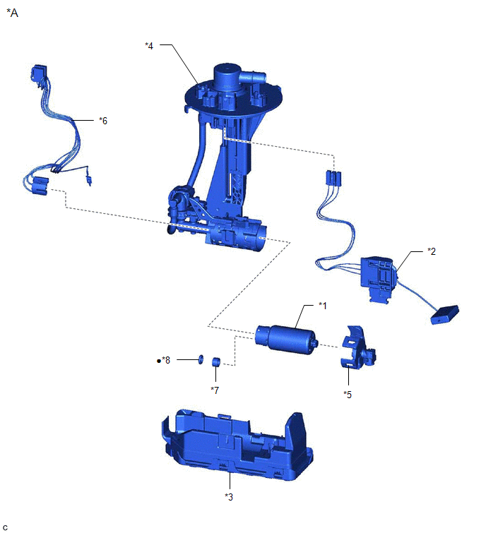
| *A | for Type B | - | - |
| *1 | FUEL PUMP | *2 | FUEL SENDER GAUGE ASSEMBLY |
| *3 | FUEL SUB-TANK SUB-ASSEMBLY | *4 | FUEL SUCTION PLATE SUB-ASSEMBLY |
| *5 | NO. 2 FUEL SUCTION SUPPORT | *6 | FUEL PUMP HARNESS |
| *7 | FUEL PUMP SPACER | *8 | O-RING |
| ● | Non-reusable part | - | - |
READ NEXT:
 Removal
REMOVAL CAUTION / NOTICE / HINT The necessary procedures (adjustment, calibration, initialization or registration) that must be performed after parts are removed and installed, or replaced during fuel
Disassembly
DISASSEMBLY CAUTION / NOTICE / HINT NOTICE: Do not disconnect the tube shown in the illustration when disassembling the fuel suction tube with pump and gauge assembly. Doing so will cause reassembly o
Inspection
INSPECTION PROCEDURE 1. INSPECT FUEL PUMP (a) Measure the resistance according to the value(s) in the table below. Standard Resistance: Tester Connection Specified Condition U - V 0.05
SEE MORE:
Diagnostic Trouble Code Chart
DIAGNOSTIC TROUBLE CODE CHART Power Trunk Lid System DTC No. Detection Item Link B2205 Kick Sensor Circuit B2222 PBD/PTL Pulse Sensor B2225 PBD/PTL Motor Clutch Malfunction B2250 PBD/PTL Closer Operation B2251 PBD/PTL Closer Switch U0
Throttle/Pedal Position Sensor/Switch "A"/"B" Voltage Correlation Signal Cross Coupled (P21352B)
DESCRIPTION Refer to DTC P012011. Click here DTC No. Detection Item DTC Detection Condition Trouble Area MIL Memory Note P21352B Throttle/Pedal Position Sensor/Switch "A"/"B" Voltage Correlation Signal Cross Coupled The difference between the output voltage of VTA1 and VTA2
