Lexus ES: Vehicle Approaching Speaker (for Front Side)
Components
COMPONENTS
ILLUSTRATION
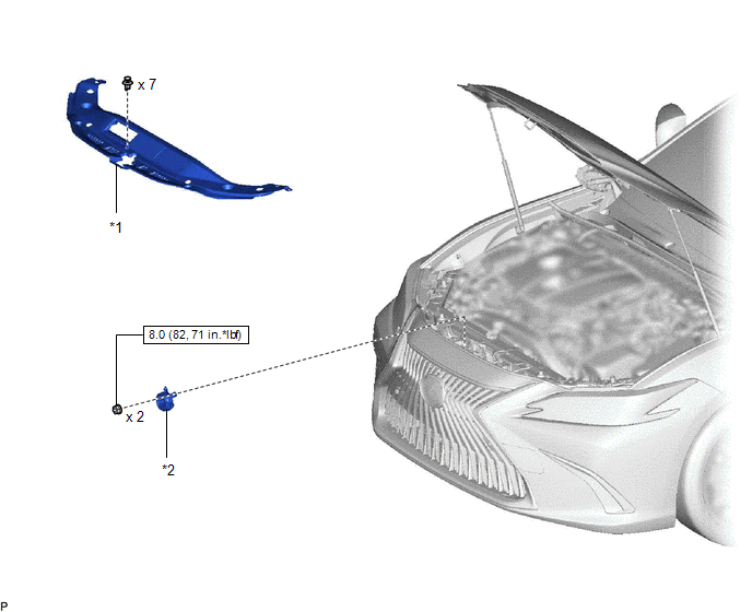
| *1 | COOL AIR INTAKE DUCT SEAL | *2 | VEHICLE APPROACHING SPEAKER ASSEMBLY |
.png) | N*m (kgf*cm, ft.*lbf): Specified torque | - | - |
Removal
REMOVAL
PROCEDURE
1. REMOVE COOL AIR INTAKE DUCT SEAL
Click here .gif)
2. REMOVE VEHICLE APPROACHING SPEAKER ASSEMBLY
| (a) Remove the 2 nuts. |
|
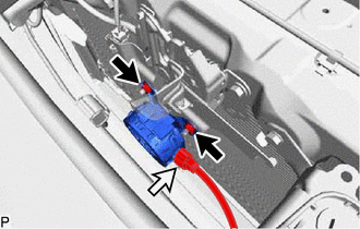
(b) Disconnect the connector to remove the vehicle approaching speaker assembly.
Inspection
INSPECTION
PROCEDURE
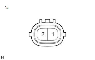
1. INSPECT VEHICLE APPROACHING SPEAKER ASSEMBLY
| (a) Measure the resistance according to the value(s) in the table below. Standard Resistance:
HINT: Make sure that the vehicle approaching speaker assembly is securely installed and not loose. If the result is not as specified, replace the vehicle approaching speaker assembly. |
|
Installation
INSTALLATION
PROCEDURE
1. INSTALL VEHICLE APPROACHING SPEAKER ASSEMBLY
(a) Connect the connector.
(b) Install the vehicle approaching speaker assembly with the 2 nuts.
Torque:
8.0 N·m {82 kgf·cm, 71 in·lbf}
2. INSTALL COOL AIR INTAKE DUCT SEAL
Click here .gif)
READ NEXT:
 Vehicle Approaching Speaker Ecu
ComponentsCOMPONENTS ILLUSTRATION *1 VEHICLE APPROACHING SPEAKER CONTROLLER - - N*m (kgf*cm, ft.*lbf): Specified torque - - RemovalREMOVAL PROCEDURE 1. REMOVE RADIO RECEIVER
Precaution
PRECAUTION PRECAUTION FOR DISCONNECTING CABLE FROM NEGATIVE AUXILIARY BATTERY TERMINAL NOTICE: When disconnecting the cable from the negative (-) auxiliary battery terminal, initialize the following s
SEE MORE:
Data List / Active Test
DATA LIST / ACTIVE TEST DATA LIST NOTICE: In the table below, the values listed under "Normal Condition" are reference values. Do not depend solely on these reference values when deciding whether a part is faulty or not. HINT: Using the Techstream to read the Data List allows the values or states of
Motor Control Relay Stuck ON (B2345)
DESCRIPTION This DTC will be stored if the operation of the sliding roof is suspended and a pulse input of 10 Hz or more is detected when the motor relay is off. DTC No. Detection Item DTC Detection Condition Trouble Area B2345 Motor Control Relay Stuck ON Position failure (When the
