Lexus ES: Skid Control ECU Communication Stop Mode
DESCRIPTION
| Detection Item | Symptom | Trouble Area |
|---|---|---|
| Skid Control ECU Communication Stop Mode | Any of the following conditions are met:
|
|
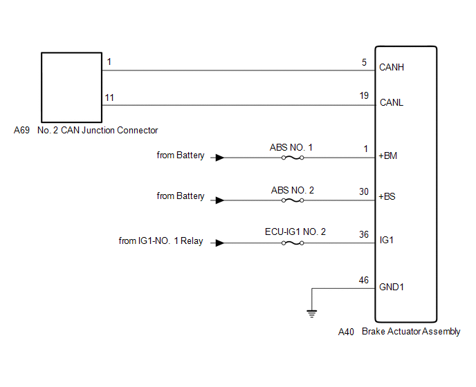
WIRING DIAGRAM
CAUTION / NOTICE / HINT
CAUTION:
When performing the confirmation driving pattern, obey all speed limits and traffic laws.
NOTICE:
-
Because the order of diagnosis is important to allow correct diagnosis, make sure to begin troubleshooting using How to Proceed with Troubleshooting when CAN communication system related DTCs are output.
Click here
.gif)
- Before measuring the resistance of the CAN bus, turn the engine switch off and leave the vehicle for 1 minute or more without operating the key or any switches, or opening or closing the doors. After that, disconnect the cable from the negative (-) battery terminal and leave the vehicle for 1 minute or more before measuring the resistance.
-
After turning the engine switch off, waiting time may be required before disconnecting the cable from the negative (-) battery terminal. Therefore, make sure to read the disconnecting the cable from the negative (-) battery terminal notices before proceeding with work.
Click here
-
After performing repairs, perform the DTC check procedure and confirm that the DTCs are not output again.
DTC check procedure: Turn the engine switch on (IG) and wait for 1 minute or more. Then operate the suspected malfunctioning system and drive the vehicle at 60 km/h (37 mph) or more for 5 minutes or more.
-
After the repair, perform the CAN bus check and check that all the ECUs and sensors connected to the CAN communication system are displayed as normal.
Click here
- Inspect the fuses for circuits related to this system before performing the following procedure.
HINT:
- Before disconnecting related connectors for inspection, push in on each connector body to check that the connector is not loose or disconnected.
- When a connector is disconnected, check that the terminals and connector body are not cracked, deformed or corroded.
PROCEDURE
| 1. | CHECK FOR OPEN IN CAN BUS LINES (BRAKE ACTUATOR ASSEMBLY BRANCH LINE) |
(a) Disconnect the cable from the negative (-) battery terminal.
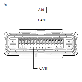
(b) Disconnect the A40 brake actuator assembly connector.
| (c) Measure the resistance according to the value(s) in the table below. Standard Resistance:
|
|
| NG | .gif) | REPAIR OR REPLACE CAN BRANCH LINES OR CONNECTOR (BRAKE ACTUATOR ASSEMBLY) |
|
.gif)
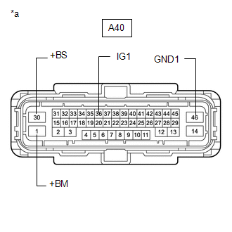
| 2. | CHECK HARNESS AND CONNECTOR (POWER SOURCE CIRCUIT) |
| (a) Measure the resistance according to the value(s) in the table below. Standard Resistance:
|
|
(b) Reconnect the cable to the negative (-) battery terminal.
(c) Measure the voltage according to the value(s) in the table below.
Standard Voltage:
| Tester Connection | Condition | Specified Condition |
|---|---|---|
| A40-36 (IG1) - Body ground | Engine switch on (IG) | 11 to 14 V |
| A40-1 (+BM) - Body ground | Always | 11 to 14 V |
| A40-30 (+BS) - Body ground | Always | 11 to 14 V |
| OK | | REPLACE BRAKE ACTUATOR ASSEMBLY |
| NG | | REPAIR OR REPLACE HARNESS OR CONNECTOR (POWER SOURCE CIRCUIT) |
READ NEXT:
 ECU Malfunction (B1003)
DESCRIPTION DTC No. Detection Item DTC Detection Condition Trouble Area Note B1003 ECU Malfunction A malfunction in the non-volatile storage of the central gateway ECU (network gate
Diagnostic Trouble Code Chart
DIAGNOSTIC TROUBLE CODE CHART Diagnostic Trouble Code Chart DTC No. Detection Item Trouble Area Link B1003 ECU Malfunction Central gateway ECU (network gateway ECU)
Data List / Active Test
DATA LIST / ACTIVE TEST NOTICE: In the table below, the values listed under "Normal Condition" are reference values. Do not depend solely on these reference values when deciding whether a part is faul
SEE MORE:
Removal
REMOVAL
CAUTION / NOTICE / HINT
The necessary procedures (adjustment, calibration, initialization, or registration)
that must be performed after parts are removed and installed, or replaced during
rear brake flexible hose removal/installation are shown below.
Necessary Procedures After Parts
Window Glass Antenna Wire
On-vehicle InspectionON-VEHICLE INSPECTION PROCEDURE 1. INSPECT WINDOW GLASS ANTENNA WIRE (a) Check the continuity of the antenna. HINT: Check for continuity at the center of each antenna wire as shown in the illustration. NOTICE:
When cleaning the glass, wipe it in the direction of the wir
