Lexus ES: Roof Drip Side Finish Moulding
Components
COMPONENTS
ILLUSTRATION
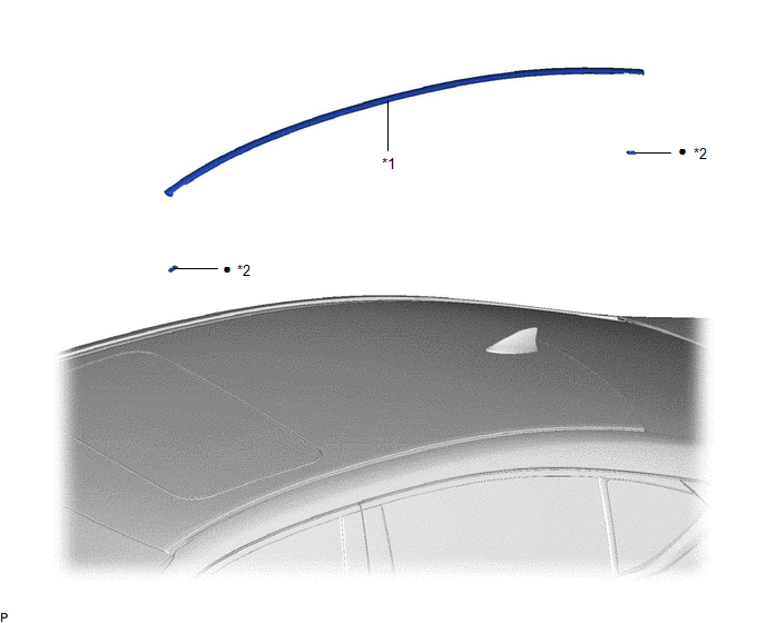
| *1 | CENTER ROOF DRIP SIDE FINISH MOULDING | *2 | NO. 1 ROOF DRIP SIDE FINISH MOULDING CLIP |
| ● | Non-reusable part | - | - |
Removal
REMOVAL
CAUTION / NOTICE / HINT
HINT:
- Use the same procedure for the RH side and LH side.
- The following procedure is for the LH side.
PROCEDURE
1. REMOVE CENTER ROOF DRIP SIDE FINISH MOULDING
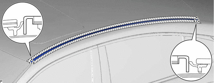
(a) Apply protective tape around the center roof drip side finish moulding as shown in the illustration.
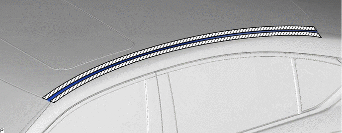
.png) | Protective Tape | - | - |
(b) Using a moulding remover, disengage the 2 clips and remove the center roof drip side finish moulding.
NOTICE:
- Do not remove the No. 1 roof drip side finish moulding clips.
- If a No. 1 roof drip side finish moulding clip is damaged or falls off, replace it with a new one.
Installation
INSTALLATION
CAUTION / NOTICE / HINT
HINT:
- Use the same procedure for the RH side and LH side.
- The following procedure is for the LH side.
PROCEDURE
1. INSTALL NO. 1 ROOF DRIP SIDE FINISH MOULDING CLIP
NOTICE:
When installing new No. 1 roof drip side finish moulding clips, remove any adhesive from the installation area of the No. 1 roof drip side finish moulding clips on the vehicle body and clean the vehicle body with a non-residue solvent.
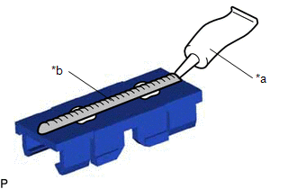
| (a) Apply a 2 to 3 mm (0.0787 to 0.118 in.) bead of adhesive (3M DP-105 or equivalent) to each new No. 1 roof drip side finish moulding clip. HINT: Adhesive strength (tensile strength): 13.7 MPa (140.0 kgf/cm2, 1987 psi) or more (when the temperature is 23°C (73°F).) |
|
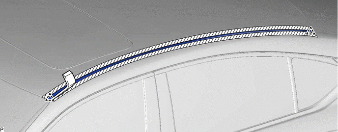
(b) Install the 2 No. 1 roof drip side finish moulding clips to the positions on the roof panel shown in the illustration. Determine the locations and firmly press and install the 2 No. 1 roof drip side finish moulding clips.
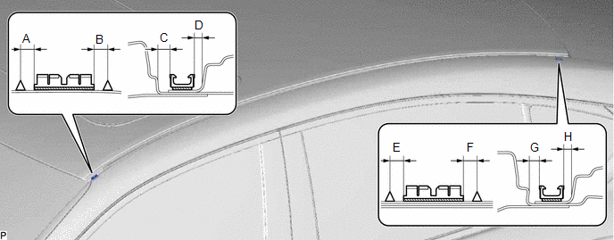
Standard Measurement:
| Area | Measurement | Area | Measurement |
|---|---|---|---|
| A | 5.0 mm (0.197 in.) | B | 5.0 mm (0.197 in.) |
| C | 4.4 mm (0.173 in.) | D | 3.1 mm (0.122 in.) |
| E | 5.0 mm (0.197 in.) | F | 5.0 mm (0.197 in.) |
| G | 3.8 mm (0.150 in.) | H | 3.0 mm (0.118 in.) |
(c) Wait at least 40 minutes before installing the center roof drip side finish moulding.
HINT:
- Initial hardening time: 40 minutes
- Complete hardening time: 24 hours
2. INSTALL CENTER ROOF DRIP SIDE FINISH MOULDING
(a) Engage the 2 clips to install the center roof drip side finish moulding as shown in the illustration.
READ NEXT:
 Components
COMPONENTS ILLUSTRATION *1 NO. 1 WINDSHIELD OUTSIDE MOULDING CLIP *2 NO. 3 WINDSHIELD OUTSIDE MOULDING CLIP *3 WINDSHIELD OUTSIDE MOULDING *4 WINDSHIELD GLASS SUB-ASSEMBLY ●
Removal
REMOVAL CAUTION / NOTICE / HINT HINT:
Use the same procedure for the RH side and LH side.
The following procedure is for the LH side.
PROCEDURE 1. REMOVE WINDSHIELD OUTSIDE MOULDING LH (a) App
SEE MORE:
Removal
REMOVAL CAUTION / NOTICE / HINT The necessary procedures (adjustment, calibration, initialization, or registration) that must be performed after parts are removed and installed, or replaced during engine oil level sensor removal/installation are shown below. Necessary Procedure After Parts Removed/I
Removal
REMOVAL CAUTION / NOTICE / HINT The necessary procedures (adjustment, calibration, initialization or registration) that must be performed after parts are removed and installed, or replaced during fuel main valve assembly removal/installation are shown below. Necessary Procedures After Parts Removed/
