Lexus ES: Removal
REMOVAL
CAUTION / NOTICE / HINT
The necessary procedures (adjustment, calibration, initialization or registration) that must be performed after parts are removed and installed, or replaced during fuel main valve assembly removal/installation are shown below.
Necessary Procedures After Parts Removed/Installed/Replaced| Replaced Part or Performed Procedure | Necessary Procedure | Effect/Inoperative Function when Necessary Procedure not Performed | Link |
|---|---|---|---|
|
*: When performing learning using the Techstream.
Click here | |||
| Battery terminal is disconnected/reconnected | Perform steering sensor zero point calibration | Lane Control System (for Gasoline Model) | |
| Pre-collision System (for Gasoline Model) | |||
| Parking Support Brake System (for Gasoline Model)* | |||
| Lighting System (for Gasoline Model) | |||
| Memorize steering angle neutral point | Parking Assist Monitor System (for Gasoline Model) | | |
| Panoramic View Monitor System (for Gasoline Model) | | ||
| Initialize power trunk lid system | Power Trunk Lid System (for Gasoline Model) | | |
| Replacement of fuel pump with filter assembly | Inspection after repair |
| |
CAUTION:
-
Never perform work on fuel system components near any possible ignition sources.
.png)
- Vaporized fuel could ignite, resulting in a serious accident.
-
Do not perform work on fuel system components without first disconnecting the cable from the negative (-) battery terminal.
.png)
- Sparks could cause vaporized fuel to ignite, resulting in a serious accident.
NOTICE:
- After the engine switch is turned off, the radio receiver assembly records various types of memory and settings. As a result, after turning the engine switch off, make sure to wait at least 85 seconds before disconnecting the cable from the negative (-) battery terminal. (for Audio and Visual System)
- After the engine switch is turned off, the radio receiver assembly records various types of memory and settings. As a result, after turning the engine switch off, make sure to wait at least 85 seconds before disconnecting the cable from the negative (-) battery terminal. (for Navigation System)
-
Do not disconnect the tube shown in the illustration when disassembling the fuel suction tube with pump and gauge assembly. Doing so will cause reassembly of the fuel suction tube with pump and gauge assembly to be impossible as the tube is pressed into the fuel suction plate sub-assembly.
.png)
*a
Tube
PROCEDURE
1. REMOVE FUEL SUCTION TUBE WITH PUMP AND GAUGE ASSEMBLY
Click here .gif)
2. REMOVE FUEL PUMP WITH FILTER ASSEMBLY
Click here
3. REMOVE FUEL MAIN VALVE ASSEMBLY
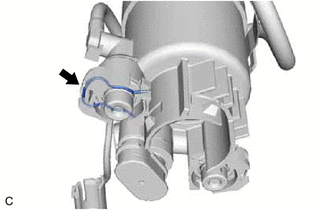
(a) Remove the fuel main valve assembly (for Low Pressure).
(1) Remove the clip from the fuel filter.
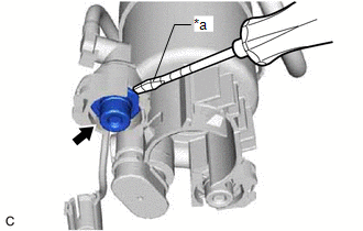
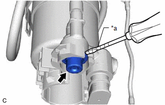
| (2) Using a screwdriver with its tip wrapped with protective tape, remove the fuel main valve assembly from the fuel filter. NOTICE:
|
|
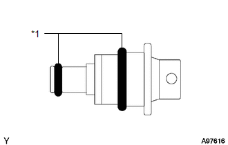
| (3) Remove the 2 O-rings from the fuel main valve assembly. |
|
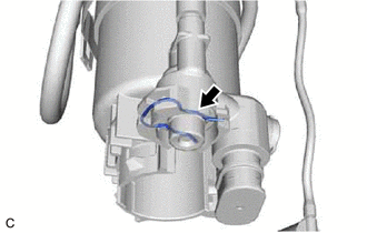
(b) Remove the fuel main valve assembly (for High Pressure).
(1) Remove the clip from the fuel filter.
| (2) Using a screwdriver with its tip wrapped with protective tape, remove the fuel main valve assembly from the fuel filter. NOTICE:
|
|
| (3) Remove the 2 O-rings from the fuel main valve assembly. |
|
READ NEXT:
 Installation
INSTALLATION PROCEDURE 1. INSTALL FUEL MAIN VALVE ASSEMBLY (a) Apply gasoline to 2 new O-rings. Then install the O-rings to the fuel main valve assembly (for Low Pressure). (b) Apply gasoline to 2 new
Components
COMPONENTS ILLUSTRATION *1 FUEL PRESSURE SENSOR (FUEL DELIVERY PIPE WITH SENSOR ASSEMBLY) - -
SEE MORE:
Diagnostic Trouble Code Chart
DIAGNOSTIC TROUBLE CODE CHART Electronically Controlled Brake System DTC No. Detection Item Link C00631C Yaw Rate Sensor Circuit Voltage Out of Range C00631F Yaw Rate Sensor Circuit Intermittent C006396 Yaw Rate Sensor Component Internal Failure C050012
Vehicle Control History
VEHICLE CONTROL HISTORY NOTICE: Make sure to record any output Vehicle Control History codes before clearing them and checking the Vehicle Control History again. CHECK VEHICLE CONTROL HISTORY (FRONT CAMERA SYSTEM) (a) Connect the Techstream to the DLC3. (b) Turn the engine switch on (IG). (c) Turn t
