Lexus ES: Removal
REMOVAL
CAUTION / NOTICE / HINT
The necessary procedures (adjustment, calibration, initialization, or registration) that must be performed after parts are removed and installed, or replaced during clearance warning ECU assembly removal/installation are shown below.
Necessary Procedure After Parts Removed/Installed/Replaced (for HV Model)| Replaced Part or Performed Procedure | Necessary Procedures | Effect/Inoperative Function When Necessary Procedures are not Performed | Link |
|---|---|---|---|
|
*: When performing learning using the Techstream.
Click here | |||
| Disconnect cable from negative auxiliary battery terminal | Perform steering sensor zero point calibration | Lane Control System | |
| Pre-collision System | |||
| Parking Support Brake System* | |||
| Lighting System | |||
| Memorize steering angle neutral point | Parking Assist Monitor System | | |
| Panoramic View Monitor System | | ||
| Initialize power trunk lid system | Power Trunk Lid System | | |
| Clearance warning ECU assembly |
|
| |
CAUTION:
Some of these service operations affect the SRS airbag system. Read the precautionary notices concerning the SRS airbag system before servicing.
.png)
Click here .gif)
NOTICE:
- After the power switch is turned off, the radio receiver assembly records various types of memory and settings. As a result, after turning the power switch off, make sure to wait at least 85 seconds before disconnecting the cable from the negative (-) auxiliary battery terminal. (for Audio and Visual System)
- After the power switch is turned off, the radio receiver assembly records various types of memory and settings. As a result, after turning the power switch off, make sure to wait at least 85 seconds before disconnecting the cable from the negative (-) auxiliary battery terminal. (for Navigation System)
| Replaced Part or Performed Procedure | Necessary Procedures | Effect/Inoperative Function When Necessary Procedures are not Performed | Link |
|---|---|---|---|
|
*: When performing learning using the Techstream.
Click here | |||
| Disconnect cable from negative battery terminal | Perform steering sensor zero point calibration | Lane Control System | |
| Pre-collision System | |||
| Parking Support Brake System* | |||
| Lighting System | |||
| Memorize steering angle neutral point | Parking Assist Monitor System | | |
| Panoramic View Monitor System | | ||
| Initialize power trunk lid system | Power Trunk Lid System | | |
| Replacement of clearance warning ECU assembly |
|
| |
CAUTION:
Some of these service operations affect the SRS airbag system. Read the precautionary notices concerning the SRS airbag system before servicing.
Click here
NOTICE:
- After the engine switch is turned off, the radio receiver assembly records various types of memory and settings. As a result, after turning the engine switch off, make sure to wait at least 85 seconds before disconnecting the cable from the negative (-) battery terminal. (for Audio and Visual System)
- After the engine switch is turned off, the radio receiver assembly records various types of memory and settings. As a result, after turning the engine switch off, make sure to wait at least 85 seconds before disconnecting the cable from the negative (-) battery terminal. (for Navigation System)
PROCEDURE
1. REMOVE LOWER NO. 2 INSTRUMENT PANEL AIRBAG ASSEMBLY
Click here
2. REMOVE GLOVE COMPARTMENT DOOR ASSEMBLY
Click here
3. REMOVE ECU INTEGRATION BOX RH
Click here
4. REMOVE CLEARANCE WARNING ECU ASSEMBLY
(a) Using a screwdriver with its tip wrapped with protective tape, disengage the claw and remove the clearance warning ECU assembly as shown in the illustration.
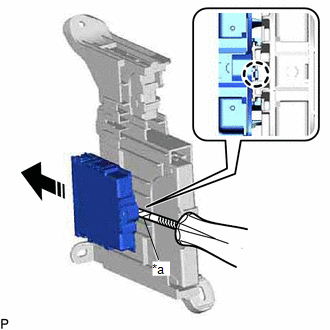
| *a | Protective Tape |
.png) | Remove in this Direction |
NOTICE:
- If the ECU integration box is deformed or damaged, replace it.
- Do not bend the claw more than necessary.
READ NEXT:
 Components
COMPONENTS ILLUSTRATION *1 COWL SIDE TRIM BOARD LH *2 FRONT DOOR OPENING TRIM COVER LH *3 FRONT DOOR SCUFF PLATE LH *4 INSTRUMENT SIDE PANEL LH *5 LOWER INSTRUMENT PANEL FINI
Inspection
INSPECTION PROCEDURE 1. INSPECT PANORAMIC VIEW MONITOR SWITCH (NO. 2 COMBINATION SWITCH ASSEMBLY) (a) Remove the panoramic view monitor switch (No. 2 combination switch assembly). Click here (b)
SEE MORE:
Switch Failure (B2342)
DESCRIPTION This DTC is stored when the sliding roof ECU (sliding roof drive gear assembly) detects that the panoramic moon roof switch (map light sub-assembly) is stuck for 30 seconds or more. DTC No. Detection Item DTC Detection Condition Trouble Area B2342 Switch Failure Sliding
Backup Battery Internal Electronic Failure (B15CC49)
DESCRIPTION This DTC is set when the DCM (telematics transceiver) detects one of the following:
The mobilephone battery voltage drops or the mobilephone battery malfunctions.
The mobilephone battery temperature is (temporarily) high.
DTC No. Detection Item DTC Detection Condition Tr
