Lexus ES: Inspection
INSPECTION
PROCEDURE
1. INSPECT PANORAMIC VIEW MONITOR SWITCH (NO. 2 COMBINATION SWITCH ASSEMBLY)
(a) Remove the panoramic view monitor switch (No. 2 combination switch assembly).
Click here .gif)
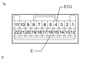
| (b) Measure the resistance according to the value(s) in the table below. Standard Resistance:
If the result is not as specified, replace the panoramic view monitor switch (No. 2 combination switch assembly). |
|
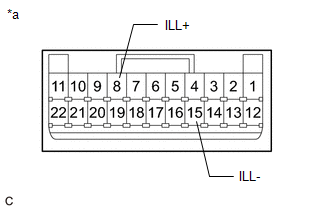
(c) Check that the switch illumination illuminates.
| (1) Apply auxiliary battery voltage to the panoramic view monitor switch (No. 2 combination switch assembly) and check that the switch illumination illuminates. OK:
If the result is not as specified, replace the panoramic view monitor switch (No. 2 combination switch assembly). |
|
(d) Install the panoramic view monitor switch (No. 2 combination switch assembly).
Click here
READ NEXT:
 Installation
INSTALLATION PROCEDURE 1. INSTALL PANORAMIC VIEW MONITOR SWITCH (NO. 2 COMBINATION SWITCH ASSEMBLY) (a) Engage the 4 claws to install the panoramic view monitor switch (No. 2 combination switch assemb
Removal
REMOVAL PROCEDURE 1. REMOVE FRONT DOOR SCUFF PLATE LH Click here 2. REMOVE COWL SIDE TRIM BOARD LH Click here 3. REMOVE FRONT DOOR OPENING TRIM COVER LH Click here 4. REMOVE INSTRUMENT SIDE PANE
SEE MORE:
ECM Communication (C124A00)
DESCRIPTION If the vehicle information stored by the skid control ECU (brake actuator assembly) does not match that sent from the ECM or a new skid control ECU (brake actuator assembly) is installed and the vehicle information has not been stored, this DTC is stored. DTC No. Detection Item DT
Customize Parameters
CUSTOMIZE PARAMETERS CUSTOMIZE PANORAMIC MOON ROOF SYSTEM NOTICE:
When the customer requests a change in a function, first make sure that the function can be customized.
Be sure to make notes of the current settings before customizing.
When troubleshooting a function, first make sure that the
