Lexus ES: Components
COMPONENTS
ILLUSTRATION
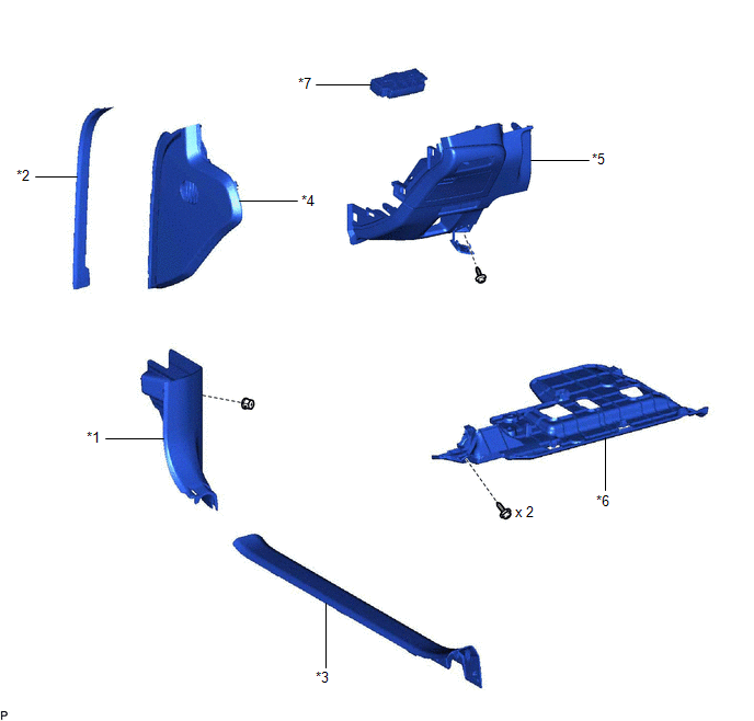
| *1 | COWL SIDE TRIM BOARD LH | *2 | FRONT DOOR OPENING TRIM COVER LH |
| *3 | FRONT DOOR SCUFF PLATE LH | *4 | INSTRUMENT SIDE PANEL LH |
| *5 | LOWER INSTRUMENT PANEL FINISH PANEL SUB-ASSEMBLY | *6 | NO. 1 INSTRUMENT PANEL UNDER COVER SUB-ASSEMBLY |
| *7 | PANORAMIC VIEW MONITOR SWITCH (NO. 2 COMBINATION SWITCH ASSEMBLY) | - | - |
READ NEXT:
 Inspection
INSPECTION PROCEDURE 1. INSPECT PANORAMIC VIEW MONITOR SWITCH (NO. 2 COMBINATION SWITCH ASSEMBLY) (a) Remove the panoramic view monitor switch (No. 2 combination switch assembly). Click here (b)
Installation
INSTALLATION PROCEDURE 1. INSTALL PANORAMIC VIEW MONITOR SWITCH (NO. 2 COMBINATION SWITCH ASSEMBLY) (a) Engage the 4 claws to install the panoramic view monitor switch (No. 2 combination switch assemb
Removal
REMOVAL PROCEDURE 1. REMOVE FRONT DOOR SCUFF PLATE LH Click here 2. REMOVE COWL SIDE TRIM BOARD LH Click here 3. REMOVE FRONT DOOR OPENING TRIM COVER LH Click here 4. REMOVE INSTRUMENT SIDE PANE
SEE MORE:
Operation Check
OPERATION CHECK CHECK ELECTRICAL REMOTE CONTROL MIRROR FUNCTION (a) Turn the engine switch on (IG). (b) b. With the mirror select switch driver side switch on, check that the outer rear view mirror assembly (driver door) surface moves up, down, left and right normally (c) With the mirror select swit
Data List / Active Test
DATA LIST / ACTIVE TEST ACTIVE TEST HINT: Using the Techstream to perform Active Tests allows relays, VSVs, actuators and other items to be operated without removing any parts. This non-intrusive functional inspection can be very useful because intermittent operation may be discovered before parts o
© 2016-2026 Copyright www.lexguide.net
