Lexus ES: Electric Parking Brake does not Operate
WIRING DIAGRAM

CAUTION / NOTICE / HINT
NOTICE:
- The electric parking brake may still operate up to 20 seconds after the engine switch is turned off. Before disconnecting connectors or fuses, turn the engine switch off and wait 20 seconds or more.
- Inspect the fuses for circuits related to this system before performing the following procedure.
-
After replacing the skid control ECU (brake actuator assembly), perform acceleration sensor zero point calibration and store system information memorization.
Click here
.gif)
- When replacing the skid control ECU (brake actuator assembly), operate the electric parking brake switch assembly as the parking brake indicator light blinks (red) when the engine switch is first turned on (IG).
HINT:
Even if the electric parking brake is operating normally, the parking brake indicator light (red) on the combination meter may be malfunctioning.
PROCEDURE
| 1. | CHECK CAN COMMUNICATION SYSTEM |
(a) Check if CAN communication system DTCs are output.
Chassis > Brake/EPB > Trouble Codes| Result | Proceed to |
|---|---|
| DTCs are not output | A |
| DTCs are output | B |
| B | .gif) | GO TO CAN COMMUNICATION SYSTEM |
|
.gif)
| 2. | VEHICLE OPERATION CHECK |
(a) When the vehicle's tires are lifted off the ground and the Techstream is used to operate the electric parking brake, check the condition of the rear tires.
Click here
| Result | Proceed to |
|---|---|
| Lock and release operation is normal and parking brake indicator light turns off or blinks (red) | A |
| Lock and release operation is malfunctioning and parking brake indicator light illuminates (red) or turns off according to switch operation | B |
| Lock and release operation is malfunctioning and parking brake indicator light turns off or blinks (red) | C |
| B | | INSPECT REAR BRAKE |
| C | | GO TO STEP 4 |
|
| 3. | INSPECT COMBINATION METER ASSEMBLY |
(a) Perform the Active Test of the combination meter assembly using the Techstream.
Body Electrical > Combination Meter > Active Test| Tester Display |
|---|
| Indicat. Park |
(b) Check the combination meter assembly.
OK:
Parking brake indicator light (red) turns on or off in accordance with Techstream operation.
| OK | | REPLACE SKID CONTROL ECU (BRAKE ACTUATOR ASSEMBLY) |
| NG | | GO TO METER / GAUGE SYSTEM |
| 4. | CHECK HARNESS AND CONNECTOR (+BS TERMINAL VOLTAGE) |
(a) Turn the engine switch off.
| (b) Disconnect the A40 skid control ECU (brake actuator assembly) connector. |
|
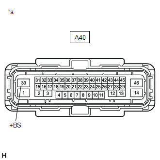
(c) Measure the voltage according to the value(s) in the table below.
Standard Voltage:
| Tester Connection | Condition | Specified Condition |
|---|---|---|
| A40-30 (+BS) - Body ground | Engine switch off | 11 to 14 V |
| NG | | REPAIR OR REPLACE HARNESS OR CONNECTOR |
|
| 5. | CHECK HARNESS AND CONNECTOR (IG1 TERMINAL VOLTAGE) |
(a) Turn the engine switch off.
| (b) Disconnect the A40 skid control ECU (brake actuator assembly) connector. |
|
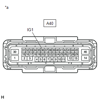
(c) Measure the voltage according to the value(s) in the table below.
Standard Voltage:
| Tester Connection | Condition | Specified Condition |
|---|---|---|
| A40-36 (IG1) - Body ground | Engine switch on (IG) | 11 to 14 V |
| OK | | REPLACE SKID CONTROL ECU (BRAKE ACTUATOR ASSEMBLY) |
| NG | | REPAIR OR REPLACE HARNESS OR CONNECTOR |
READ NEXT:
 Electric Parking Brake System AUTO Function Circuit
DESCRIPTION The skid control ECU (brake actuator assembly) receives shift position signals from the ECM via CAN communication to control the electric parking brake system AUTO function (IG-OFF linked
Electric Parking Brake System AUTO Function Circuit
DESCRIPTION The skid control ECU (brake actuator assembly) receives shift position signals from the ECM via CAN communication to control the electric parking brake system AUTO function (IG-OFF linked
Fail-safe Chart
FAIL-SAFE CHART DTC Trouble Area Parking Brake Indicator Light (Red) Brake System Warning Light (Yellow) Fail-safe Deactivation Condition C059704 Skid control ECU (brake actuator asse
SEE MORE:
Components
COMPONENTS ILLUSTRATION *A for Gasoline Model 2WD *B for RH Side *C for LH Side - - *1 NO. 1 FLOOR UNDER COVER *2 NO. 2 FLOOR UNDER COVER N*m (kgf*cm, ft.*lbf): Specified torque - - ILLUSTRATION *A for HV Model *B for RH Side *C for LH Side
Reassembly
REASSEMBLY PROCEDURE 1. INSTALL REAR BUMPER REINFORCEMENT Click here 2. INSTALL REAR BUMPER PROTECTOR INSERT LH Click here 3. INSTALL REAR BUMPER PROTECTOR INSERT RH HINT: Use the same procedure as for the LH side. 4. INSTALL REAR BUMPER PROTECTOR LH Click here 5. INSTALL REAR BUMPER PROTECTOR
