Lexus ES: Removal
REMOVAL
CAUTION / NOTICE / HINT
The necessary procedures (adjustment, calibration, initialization, or registration) that must be performed after parts are removed and installed, or replaced during navigation antenna assembly removal/installation are shown below.
Necessary Procedure After Parts Removed/Installed/Replaced (for HV Model)| Replaced Part or Performed Procedure | Necessary Procedures | Effect/Inoperative Function When Necessary Procedures are not Performed | Link |
|---|---|---|---|
|
*: When performing learning using the Techstream.
Click here | |||
| Disconnect cable from negative auxiliary battery terminal | Perform steering sensor zero point calibration | Lane Control System | |
| Pre-collision System | |||
| Parking Support Brake System* | |||
| Lighting System | |||
| Memorize steering angle neutral point | Parking Assist Monitor System | | |
| Panoramic View Monitor System | | ||
| Initialize power trunk lid system | Power Trunk Lid System | | |
CAUTION:
Some of these service operations affect the SRS airbag system. Read the precautionary notices concerning the SRS airbag system before servicing.
.png)
Click here .gif)
NOTICE:
- After the power switch is turned off, the radio receiver assembly records various types of memory and settings. As a result, after turning the power switch off, make sure to wait at least 85 seconds before disconnecting the cable from the negative (-) auxiliary battery terminal. (for Audio and Visual System)
- After the power switch is turned off, the radio receiver assembly records various types of memory and settings. As a result, after turning the power switch off, make sure to wait at least 85 seconds before disconnecting the cable from the negative (-) auxiliary battery terminal. (for Navigation System)
| Replaced Part or Performed Procedure | Necessary Procedures | Effect/Inoperative Function When Necessary Procedures are not Performed | Link |
|---|---|---|---|
|
*: When performing learning using the Techstream.
Click here | |||
| Disconnect cable from negative battery terminal | Perform steering sensor zero point calibration | Lane Control System | |
| Pre-collision System | |||
| Parking Support Brake System* | |||
| Lighting System | |||
| Memorize steering angle neutral point | Parking Assist Monitor System | | |
| Panoramic View Monitor System | | ||
| Initialize power trunk lid system | Power Trunk Lid System | | |
CAUTION:
Some of these service operations affect the SRS airbag system. Read the precautionary notices concerning the SRS airbag system before servicing.
Click here
NOTICE:
- After the engine switch is turned off, the radio receiver assembly records various types of memory and settings. As a result, after turning the engine switch off, make sure to wait at least 85 seconds before disconnecting the cable from the negative (-) battery terminal. (for Audio and Visual System)
- After the engine switch is turned off, the radio receiver assembly records various types of memory and settings. As a result, after turning the engine switch off, make sure to wait at least 85 seconds before disconnecting the cable from the negative (-) battery terminal. (for Navigation System)
PROCEDURE
1. REMOVE INSTRUMENT PANEL SAFETY PAD SUB-ASSEMBLY
Click here
2. REMOVE NO. 2 SIDE DEFROSTER NOZZLE DUCT
Click here
3. REMOVE DEFROSTER NOZZLE ASSEMBLY
Click here
4. REMOVE NO. 3 HEATER TO REGISTER DUCT
Click here
5. REMOVE NAVIGATION ANTENNA ASSEMBLY WITH BRACKET
| (a) Disconnect the connector. |
|
.png)
(b) Disengage the 2 claws.
| (c) Remove the 2 screws and navigation antenna assembly with bracket. |
|
.png)
6. REMOVE NAVIGATION ANTENNA ASSEMBLY
(a) Disengage the 2 claws and 6 guides to remove the navigation antenna assembly as shown in the illustration.
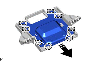
.png) | Remove in this Direction |
7. REMOVE NAVIGATION ANTENNA BRACKET
READ NEXT:
 Components
COMPONENTS ILLUSTRATION *1 CENTER INSTRUMENT CLUSTER FINISH PANEL SUB-ASSEMBLY *2 INSTRUMENT PANEL FINISH PANEL END LH *3 INSTRUMENT PANEL FINISH PANEL END RH *4 REAR UPPER CONSOLE
Installation
INSTALLATION PROCEDURE 1. INSTALL NAVIGATION ECU 2. INSTALL NO. 1 RADIO RECEIVER BRACKET (a) Install the No. 1 radio receiver bracket with the 2 screws. 3. INSTALL NAVIGATION ECU WITH BRACKET (a) Enga
SEE MORE:
GVIF Disconnected (from Park Assist/Monitoring ECU to EMV/MM Integrated Device) (B1574)
DESCRIPTION DTC No. Detection Item DTC Detection Condition Trouble Area B1574 GVIF Disconnected (from Park Assist/Monitoring ECU to EMV/MM Integrated Device) GVIF disconnected (from parking assist ECU to multi-display assembly)
Harness or connector (GVIF cable)
Multi-display
Components
COMPONENTS ILLUSTRATION *1 REAR SEAT INNER BELT ASSEMBLY LH *2 REAR CENTER SEAT LAP TYPE BELT ASSEMBLY *3 WASHER *4 REAR SEAT CUSHION ASSEMBLY *5 REAR SEAT CUSHION LOCK HOOK - - Tightening torque for "Major areas involving basic vehicle performance such as moving
