Lexus ES: Components
COMPONENTS
ILLUSTRATION
.png)
| *1 | CENTER INSTRUMENT CLUSTER FINISH PANEL SUB-ASSEMBLY | *2 | INSTRUMENT PANEL FINISH PANEL END LH |
| *3 | INSTRUMENT PANEL FINISH PANEL END RH | *4 | REAR UPPER CONSOLE PANEL SUB-ASSEMBLY |
| *5 | SHIFT LEVER KNOB SUB-ASSEMBLY | *6 | UPPER CONSOLE PANEL SUB-ASSEMBLY |
ILLUSTRATION
.png)
| *1 | COWL SIDE TRIM BOARD RH | *2 | FRONT DOOR OPENING TRIM COVER RH |
| *3 | FRONT DOOR SCUFF PLATE RH | *4 | INSTRUMENT SIDE PANEL RH |
| *5 | LOWER INSTRUMENT PANEL | *6 | LOWER INSTRUMENT PANEL LH |
| *7 | LOWER INSTRUMENT PANEL SUB-ASSEMBLY | *8 | NO. 2 INSTRUMENT PANEL UNDER COVER SUB-ASSEMBLY |
| *9 | RADIO RECEIVER ASSEMBLY WITH SWITCH | - | - |
ILLUSTRATION
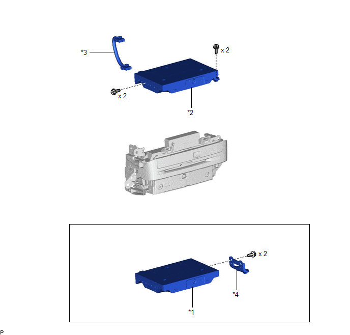
| *1 | NAVIGATION ECU | *2 | NAVIGATION ECU WITH BRACKET |
| *3 | NO. 1 NAVIGATION WIRE | *4 | NO. 1 RADIO RECEIVER BRACKET |
READ NEXT:
 Installation
INSTALLATION PROCEDURE 1. INSTALL NAVIGATION ECU 2. INSTALL NO. 1 RADIO RECEIVER BRACKET (a) Install the No. 1 radio receiver bracket with the 2 screws. 3. INSTALL NAVIGATION ECU WITH BRACKET (a) Enga
Installation
INSTALLATION PROCEDURE 1. INSTALL NAVIGATION ECU 2. INSTALL NO. 1 RADIO RECEIVER BRACKET (a) Install the No. 1 radio receiver bracket with the 2 screws. 3. INSTALL NAVIGATION ECU WITH BRACKET (a) Enga
Removal
REMOVAL PROCEDURE 1. PRECAUTION (for HV Model) NOTICE:
When replacing the radio receiver assembly or navigation ECU, always replace it with a new one. If a radio receiver assembly or navigation ECU
SEE MORE:
Transmission Fluid Temperature Sensor "A" Circuit Range/Performance (P071000)
DESCRIPTION The ATF temperature sensor converts the automatic transaxle fluid (ATF) temperature into a resistance value for use by the ECM. The ECM applies a voltage to the temperature sensor through terminal THO1 of the ECM. The sensor resistance changes with the ATF temperature. As the temperature
Removal
REMOVAL CAUTION / NOTICE / HINT The necessary procedures (adjustment, calibration, initialization or registration) that must be performed after parts are removed and installed, or replaced during radiator assembly removal/installation are shown below. Necessary Procedures After Parts Removed/Install
© 2016-2026 Copyright www.lexguide.net
