Lexus ES: Inspection
INSPECTION
PROCEDURE
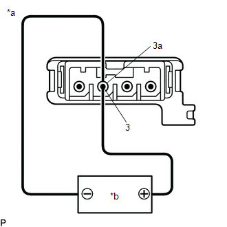
1. INSPECT NAVIGATION ANTENNA ASSEMBLY (w/o Manual (SOS) Switch)
(a) Check that the navigation antenna assembly cable is properly installed and does not have any sharp bends, pinching or loose connections.
(b) Current consumption check:
| (1) Measure the current consumption according to the value(s) in the table below. Standard Current:
NOTICE: Do not apply 6 V or more between terminals 3 and 3a. HINT: If a stable power supply is not available, connect 4 nickel-metal hydride batteries (1.2 V each) or equivalent in series. |
|
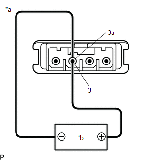
2. INSPECT NAVIGATION ANTENNA ASSEMBLY (w/ Manual (SOS) Switch)
(a) Check that the navigation antenna assembly cable is properly installed and does not have any sharp bends, pinching or loose connections.
(b) Current consumption check: (GPS)
| (1) Measure the current consumption according to the value(s) in the table below. Standard Current:
NOTICE: Do not apply 6 V or more between terminals 3 and 3a. HINT: If a stable power supply is not available, connect 4 nickel-metal hydride batteries (1.2 V each) or equivalent in series. |
|
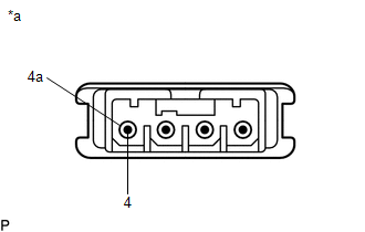
(c) Resistance check: (Telephone Sub)
| (1) Measure the resistance according to the value(s) in the table below. Standard Resistance:
|
|
READ NEXT:
 Installation
INSTALLATION PROCEDURE 1. INSTALL NAVIGATION ANTENNA BRACKET 2. INSTALL NAVIGATION ANTENNA ASSEMBLY (a) Engage the 6 guides and 2 claws to install the navigation antenna assembly as shown in the illus
Removal
REMOVAL CAUTION / NOTICE / HINT The necessary procedures (adjustment, calibration, initialization, or registration) that must be performed after parts are removed and installed, or replaced during nav
SEE MORE:
How To Proceed With Troubleshooting
CAUTION / NOTICE / HINT HINT:
Use the following procedure to troubleshoot the fuel lid opener system.
*: Use the Techstream.
PROCEDURE 1. VEHICLE BROUGHT TO WORKSHOP
NEXT 2. CUSTOMER PROBLEM ANALYSIS HINT:
In troubleshooting, confirm that the problem sym
Moon roof
Use the overhead switches to open
and close the moon roof and tilt it
up and down.
Operating the moon roof
■ Opening and closing
Opens the moon roof*
The moon roof stops slightly before the
fully open position to reduce wind noise.
Press the switch again to fully open the
moon ro
