Lexus ES: Removal
REMOVAL
CAUTION / NOTICE / HINT
The necessary procedures (adjustment, calibration, initialization, or registration) that must be performed after parts are removed and installed, or replaced during telephone and GPS antenna assembly removal/installation are shown below.
Necessary Procedure After Parts Removed/Installed/Replaced (for HV Model)| Replaced Part or Performed Procedure | Necessary Procedures | Effect/Inoperative Function When Necessary Procedures are not Performed | Link |
|---|---|---|---|
|
*: When performing learning using the Techstream.
Click here | |||
| Disconnect cable from negative auxiliary battery terminal | Perform steering sensor zero point calibration | Lane Control System | |
| Pre-collision System | |||
| Parking Support Brake System* | |||
| Lighting System | |||
| Memorize steering angle neutral point | Parking Assist Monitor System | | |
| Panoramic View Monitor System | | ||
| Initialize power trunk lid system | Power Trunk Lid System | | |
CAUTION:
Some of these service operations affect the SRS airbag system. Read the precautionary notices concerning the SRS airbag system before servicing.
.png)
Click here .gif)
NOTICE:
- After the power switch is turned off, the radio receiver assembly records various types of memory and settings. As a result, after turning the power switch off, make sure to wait at least 85 seconds before disconnecting the cable from the negative (-) auxiliary battery terminal. (for Audio and Visual System)
- After the power switch is turned off, the radio receiver assembly records various types of memory and settings. As a result, after turning the power switch off, make sure to wait at least 85 seconds before disconnecting the cable from the negative (-) auxiliary battery terminal. (for Navigation System)
| Replaced Part or Performed Procedure | Necessary Procedures | Effect/Inoperative Function When Necessary Procedures are not Performed | Link |
|---|---|---|---|
|
*: When performing learning using the Techstream.
Click here | |||
| Disconnect cable from negative battery terminal | Perform steering sensor zero point calibration | Lane Control System | |
| Pre-collision System | |||
| Parking Support Brake System* | |||
| Lighting System | |||
| Memorize steering angle neutral point | Parking Assist Monitor System | | |
| Panoramic View Monitor System | | ||
| Initialize power trunk lid system | Power Trunk Lid System | | |
CAUTION:
Some of these service operations affect the SRS airbag system. Read the precautionary notices concerning the SRS airbag system before servicing.
Click here
NOTICE:
- After the engine switch is turned off, the radio receiver assembly records various types of memory and settings. As a result, after turning the engine switch off, make sure to wait at least 85 seconds before disconnecting the cable from the negative (-) battery terminal. (for Audio and Visual System)
- After the engine switch is turned off, the radio receiver assembly records various types of memory and settings. As a result, after turning the engine switch off, make sure to wait at least 85 seconds before disconnecting the cable from the negative (-) battery terminal. (for Navigation System)
PROCEDURE
1. REMOVE INSTRUMENT PANEL SAFETY PAD SUB-ASSEMBLY
Click here
2. REMOVE NO. 2 SIDE DEFROSTER NOZZLE DUCT
Click here
3. REMOVE DEFROSTER NOZZLE ASSEMBLY
Click here
4. REMOVE NO. 3 HEATER TO REGISTER DUCT
Click here
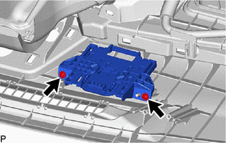
5. REMOVE TELEPHONE AND GPS ANTENNA ASSEMBLY WITH BRACKET
| (a) Disconnect the connector. |
|
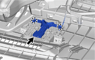
(b) Disengage the 2 claws.
| (c) Remove the 2 screws and telephone and GPS antenna assembly with bracket. |
|
6. REMOVE TELEPHONE AND GPS ANTENNA ASSEMBLY
(a) Disengage the 2 claws and 6 guides to remove the telephone and GPS antenna assembly as shown in the illustration.
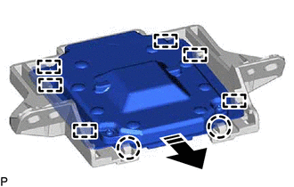
.png) | Remove in this Direction |
7. REMOVE TELEPHONE AND GPS ANTENNA BRACKET
READ NEXT:
 Components
COMPONENTS ILLUSTRATION *1 TELEPHONE AND GPS ANTENNA CORD - -
Installation
INSTALLATION PROCEDURE 1. INSTALL TELEPHONE AND GPS ANTENNA CORD (a) Engage the 5 clamps to install the telephone and GPS antenna cord. (b) Connect the connector. 2. INSTALL ROOF HEADLINING ASSEMBLY C
SEE MORE:
Components
COMPONENTS ILLUSTRATION *1 FRONT FLOOR COVER LH *2 FRONT FLOOR COVER RH N*m (kgf*cm, ft.*lbf): Specified torque - - ILLUSTRATION *1 CENTER FLOOR CROSSMEMBER BRACE *2 FRONT CENTER FLOOR BRACE N*m (kgf*cm, ft.*lbf): Specified torque - - ILLUSTRATION
Initialization
INITIALIZATION INITIALIZE PARKING ASSIST MONITOR SYSTEM (a) When "!" mark is displayed on the image of the area behind the vehicle, perform the following procedure to correct the steering angle neutral point. (1) Fully turn the steering wheel to the right and left on flat ground. NOTICE: Memorizing
