Lexus ES: Removal
REMOVAL
CAUTION / NOTICE / HINT
The necessary procedures (adjustment, calibration, initialization or registration) that must be performed after parts are removed and installed, or replaced during battery state sensor removal/installation are shown below.
Necessary Procedures After Parts Removed/Installed/Replaced| Replaced Part or Performed Procedure | Necessary Procedure | Effect/Inoperative Function when Necessary Procedure not Performed | Link |
|---|---|---|---|
|
*1: When performing learning using the Techstream.
Click here | |||
| Auxiliary battery terminal is disconnected/reconnected | Perform steering sensor zero point calibration | Lane Control System | |
| Pre-collision System | |||
| Parking Support Brake System* | |||
| Lighting System | |||
| Memorize steering angle neutral point | Parking assist monitor system | | |
| Panoramic view monitor system | | ||
| Initialize power trunk lid system | Power Trunk Lid System | | |
.gif)
NOTICE:
- After the power switch is turned off, the radio receiver assembly records various types of memory and settings. As a result, after turning the power switch off, make sure to wait at least 85 seconds before disconnecting the cable from the negative (-) auxiliary battery terminal. (for Audio and Visual System)
- After the power switch is turned off, the radio receiver assembly records various types of memory and settings. As a result, after turning the power switch off, make sure to wait at least 85 seconds before disconnecting the cable from the negative (-) auxiliary battery terminal. (for Navigation System)
PROCEDURE
1. REMOVE BATTERY STATE SENSOR ASSEMBLY
(a) Turn back the luggage compartment trim cover RH as shown in the illustration.
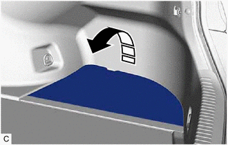
.png) | Remove in this Direction |
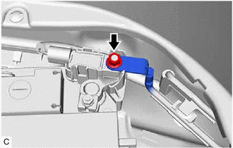
| (b) Remove the nut and disconnect the No.2 frame wire from the battery state sensor assembly. NOTICE: When disconnecting the engine wire, some systems need to be initialized after the engine wire is reconnected. Click here |
|
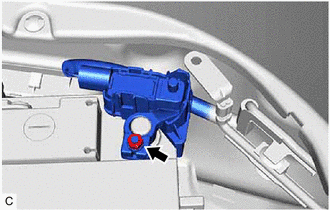
| (c) Loosen the nut and remove the battery state sensor assembly from the auxiliary battery. |
|
| (d) Disconnect the battery state sensor assembly connector. |
|
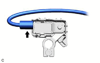
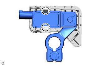
| (e) Disengage the 2 claws to remove the battery state sensor assembly from the battery current sensor holder. |
|
READ NEXT:
 Components
COMPONENTS ILLUSTRATION *1 BATTERY STATE SENSOR ASSEMBLY *2 WIRE HARNESS *3 BATTERY CURRENT SENSOR HOLDER *4 NO.2 FRAME WIRE Tightening torque for "Major areas involving bas
When Auxiliary Battery Is Discharged
WHEN AUXILIARY BATTERY IS DISCHARGED WHEN AUXILIARY BATTERY IS DISCHARGED (a) When the auxiliary battery is discharged. NOTICE: The booster terminal can only be used to rescue this vehicle and can not
SEE MORE:
Reassembly
REASSEMBLY PROCEDURE 1. CLEAN VACUUM PUMP HOUSING (a) Clean the inside surface of the vacuum pump housing. 2. INSTALL VACUUM PUMP ROTOR (a) Clean the vacuum pump rotor. (b) Apply engine oil to the areas of the vacuum pump rotor shown in the illustration. Engine Oil (c) Install the vacuum p
Headlight Swivel ECU LH Communication (B2410,B2411)
DESCRIPTION Each headlight ECU sub-assembly and headlight swivel motor communicate via LIN communication. The headlight swivel motor operates according to power supplied and automatic headlight beam level control signals from its respective headlight ECU sub-assembly and sends its operating state to
