Lexus ES: Removal
REMOVAL
CAUTION / NOTICE / HINT
HINT:
- Use the same procedure for the RH side and LH side.
- The following procedure is for the LH side.
PROCEDURE
1. REMOVE OUTER MIRROR
(a) Apply protective tape to the areas shown in the illustration.
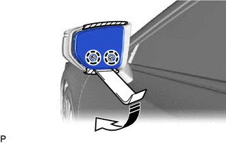
.png) | Protective Tape |
.png) | Move in this Direction |
(b) Push the upper part of the mirror surface and tilt it.
(c) Using a moulding remover, disengage the 2 claws on the lower part of the outer mirror as shown in the illustration.
NOTICE:
Do not push the outer mirror with excessive force. Doing so may cause the actuator to come off or break the mirror surface.
(d) Push the lower part of the mirror surface and tilt it.
(e) w/o Blind Spot Monitor System:
(1) Using a moulding remover, disengage the 2 claws on the upper part of the outer mirror as shown in the illustration.
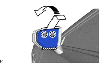
| | Move in this Direction |
NOTICE:
Do not push the outer mirror with excessive force. Doing so may cause the actuator to come off or break the mirror surface.
| (2) Disengage the clamp. |
|
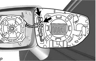
(3) Disconnect the 2 connectors.
| (4) Disengage the clamp. |
|
(5) Disengage the claw.
(6) Disconnect the connector to remove the outer mirror.
(f) w/ Blind Spot Monitor System:
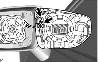
(1) Using a moulding remover, disengage the 2 claws on the upper part of the outer mirror as shown in the illustration.

| | Move in this Direction |
NOTICE:
Do not push the outer mirror with excessive force. Doing so may cause the actuator to come off or break the mirror surface.
| (2) Disengage the clamp. |
|
(3) Disconnect the 2 connectors.
| (4) Disengage the clamp. |
|
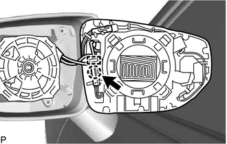
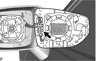
(5) Disengage the claw.
(6) Disconnect the connector.
| (7) Disengage the clamp. |
|
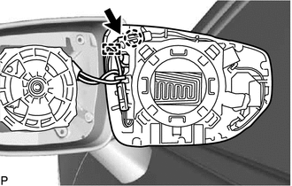
(8) Disengage the claw.
(9) Disconnect the connector to remove the outer mirror.
READ NEXT:
 Inspection
INSPECTION PROCEDURE 1. INSPECT OUTER MIRROR RH (a) Check the outer mirror heater operation. (1) Measure the resistance according to the value(s) in the table below. Standard Resistance: Tester
Installation
INSTALLATION CAUTION / NOTICE / HINT HINT:
Use the same procedure for the RH side and LH side.
The following procedure is for the LH side.
PROCEDURE 1. INSTALL OUTER MIRROR (a) w/o Blind Spot
SEE MORE:
Vehicle Information Unmatched (C168D)
DESCRIPTION This DTC is stored if the rear television camera assembly judges as a result of its self check that the vehicle information received from the main body ECU (multiplex network body ECU) via CAN communication and the vehicle information stored in the rear television camera assembly do not
Terminals Of Ecu
TERMINALS OF ECU STEREO COMPONENT EQUALIZER ASSEMBLY Terminal No. (Symbol) Wiring Color Terminal Description Condition Specified Condition G15-1 (CANH) P CAN communication signal - - G15-2 (ACK1) V Serial communication (UART) signal - - G15-3 (NEI) - G15-28 (G
