Lexus ES: Terminals Of Ecu
TERMINALS OF ECU
STEREO COMPONENT EQUALIZER ASSEMBLY

| Terminal No. (Symbol) | Wiring Color | Terminal Description | Condition | Specified Condition |
|---|---|---|---|---|
| G15-1 (CANH) | P | CAN communication signal | - | - |
| G15-2 (ACK1) | V | Serial communication (UART) signal | - | - |
| G15-3 (NEI) - G15-28 (GND) | LA-B - LA | Engine pulse signal | Idling with warm engine | Pulse generation (See waveform 1) |
| G15-5 (MC3+) - G15-28 (GND) | W - LA | Active noise control microphone input signal | No. 3 active noise control microphone tapped with finger | Pulse generation |
| G15-6 (MC2+) - G15-28 (GND) | W - LA | Active noise control microphone input signal | No. 2 active noise control microphone tapped with finger | Pulse generation |
| G15-7 (MC1+) - G15-28 (GND) | V - LA | Active noise control microphone input signal | No. 1 active noise control microphone tapped with finger | Pulse generation |
| G15-10 (CH3+) - G15-28 (GND) | W- LA | Active noise control microphone output signal | Active noise control system operating | Pulse generation |
| G15-11 (CH2+) - G15-28 (GND) | L - LA | Active noise control microphone output signal | Active noise control system operating | Pulse generation |
| G15-12 (CH1+) - G15-28 (GND) | BR - LA | Active noise control microphone output signal | Active noise control system operating | Pulse generation |
| G15-13 (ACC) - G15-28 (GND) | P - LA | Power source (ACC) | Engine switch on (ACC) | 11 to 14 V |
| G15-14 (+B) - G15-28 (GND) | LA-R - LA | Power source | Always | 11 to 14 V |
| G15-15 (CANL) | W | CAN communication signal | - | - |
| G15-16 (ACK2) | BE | Serial communication (UART) signal | - | - |
| G15-17 (ACNT) - G15-28 (GND) | SB - LA | Active noise control system control signal | Engine switch on (IG) | Below 1 V |
| Engine switch on (ACC) | 4.5 V or higher | |||
| G15-19 (MC3-) - G15-28 (GND) | SB - LA | Active noise control microphone input signal | Always | Below 1 Ω |
| G15-20 (MC2-) - G15-28 (GND) | SB - LA | Active noise control microphone input signal | Always | Below 1 Ω |
| G15-21 (MC1-) - G15-28 (GND) | LG - LA | Active noise control microphone input signal | Always | Below 1 Ω |
| G15-24 (CH3-) - G15-28 (GND) | Y - LA | Active noise control microphone output signal | Active noise control system operating | Pulse generation |
| G15-25 (CH2-) - G15-28 (GND) | R - LA | Active noise control microphone output signal | Active noise control system operating | Pulse generation |
| G15-26 (CH1-) - G15-28 (GND) | G - LA | Active noise control microphone output signal | Active noise control system operating | Pulse generation |
| G15-27 (IGN) - G15-28 (GND) | LA-SB - LA | Power source (IG) | Engine switch on (IG) | 11 to 14 V |
| G15-28 (GND) - Body ground | LA - Body ground | Ground | Always | Below 1 Ω |
(a) Waveform 1
HINT:
The oscilloscope waveform shown in the illustration is an example for reference only. The waveform fluctuates according to engine speed.
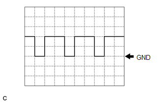
| Item | Condition |
|---|---|
| Measurement terminal | G15-3 (NEI) - G15-28 (GND) |
| Tool setting | 5 V/DIV., 20 ms./DIV. |
| Vehicle condition | Idling after warming up |
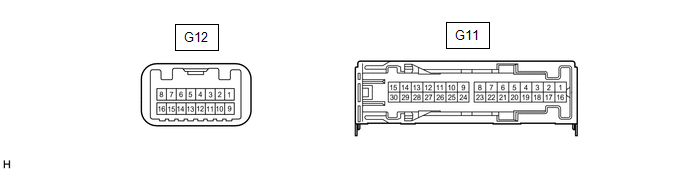
STEREO COMPONENT AMPLIFIER ASSEMBLY
| Terminal No. (Symbol) | Wiring Color | Terminal Description | Condition | Specified Condition |
|---|---|---|---|---|
| G12-2 (ACK1) | V | Serial communication (UART) signal | - | - |
| G12-3 (ACNT) - G11-3 (GND) | SB - W-B | Active noise control system control signal | Active noise control system operating | Below 1 V |
| Active noise control system not operating | 4.5 V or higher | |||
| G12-6 (AN3+) - G11-3 (GND) | W - W-B | Active noise control microphone input signal | Active noise control system operating | Pulse generation |
| G12-7 (AN2+) - G11-3 (GND) | L - W-B | Active noise control microphone input signal | Active noise control system operating | Pulse generation |
| G12-8 (AN1+) - G11-3 (GND) | BR - W-B | Active noise control microphone input signal | Active noise control system operating | Pulse generation |
| G12-10 (ACK2) | BE | Serial communication (UART) signal | - | - |
| G12-13 (ASG1) - G11-3 (GND) | Shielded - W-B | Shield ground | Always | Below 1 Ω |
| G12-14 (AN3-) - G11-3 (GND) | Y - W-B | Active noise control microphone input signal | Active noise control system operating | Pulse generation |
| G12-15 (AN2-) - G11-3 (GND) | R - W-B | Active noise control microphone input signal | Active noise control system operating | Pulse generation |
| G12-16 (AN1-) - G11-3 (GND) | G - W-B | Active noise control microphone input signal | Active noise control system operating | Pulse generation |
READ NEXT:
 Lost Communication With ECM/PCM "A" Missing Message (U010087,U012987,U014087,U016487)
DESCRIPTION These DTCs are stored when a malfunction occurs in the CAN communication circuit. DTC No. Detection Item DTC Detection Condition Trouble Area U010087 Lost Communication With
ANC ECU EEPROM Data Memory Failure (B1AA044)
DESCRIPTION This DTC is stored when a malfunction occurs in the stereo component equalizer assembly. DTC No. Detection Item DTC Detection Condition Trouble Area B1AA044 ANC ECU EEPROM D
SEE MORE:
Removal
REMOVAL CAUTION / NOTICE / HINT The necessary procedures (adjustment, calibration, initialization, or registration) that must be performed after parts are removed and installed, or replaced during rear door window frame moulding removal/installation are shown below. Necessary Procedure After Parts R
Removal
REMOVAL CAUTION / NOTICE / HINT The necessary procedures (adjustment, calibration, initialization, or registration) that must be performed after parts are removed and installed, or replaced during rear combination light assembly removal/installation are shown below. Necessary Procedure After Parts R
