Lexus ES: Removal
REMOVAL
CAUTION / NOTICE / HINT
The necessary procedures (adjustment, calibration, initialization, or registration) that must be performed after parts are removed and installed, or replaced during rear combination light assembly removal/installation are shown below.
Necessary Procedure After Parts Removed/Installed/Replaced (for HV Model)| Replaced Part or Performed Procedure | Necessary Procedure | Effect/Inoperative Function When Necessary Procedures are not Performed | Link |
|---|---|---|---|
|
*1: w/ Hands Free Power Trunk Lid
*2: When performing learning using the Techstream. Click here | |||
| Disconnect cable from negative auxiliary battery terminal*1 | Perform steering sensor zero point calibration | Lane Control System (for HV Model) | |
| Pre-collision System (for HV Model) | |||
| Parking Support Brake System (for HV Model)*2 | |||
| Lighting System (for HV Model) | |||
| Memorize steering angle neutral point | Parking Assist Monitor System (for HV Model) | | |
| Panoramic View Monitor System (for HV Model) | | ||
| Initialize power trunk lid system | Power Trunk Lid System (for HV Model) | | |
| Rear bumper assembly |
|
| |
NOTICE:
- After the power switch is turned off, the radio receiver assembly records various types of memory and settings. As a result, after turning the power switch off, make sure to wait at least 85 seconds before disconnecting the cable from the negative (-) auxiliary battery terminal. (for Audio and Visual System)
- After the power switch is turned off, the radio receiver assembly records various types of memory and settings. As a result, after turning the power switch off, make sure to wait at least 85 seconds before disconnecting the cable from the negative (-) auxiliary battery terminal. (for Navigation System)
| Replaced Part or Performed Procedure | Necessary Procedure | Effect/Inoperative Function When Necessary Procedures are not Performed | Link |
|---|---|---|---|
|
*1: w/ Hands Free Power Trunk Lid
*2: When performing learning using the Techstream. Click here | |||
| Disconnect cable from negative battery terminal*1 | Perform steering sensor zero point calibration | Lane Control System (for Gasoline Model) | |
| Pre-collision System (for Gasoline Model) | |||
| Parking Support Brake System (for Gasoline Model)*2 | |||
| Lighting System (for Gasoline Model) | |||
| Memorize steering angle neutral point | Parking Assist Monitor System (for Gasoline Model) | | |
| Panoramic View Monitor System (for Gasoline Model) | | ||
| Initialize power trunk lid system | Power Trunk Lid System (for Gasoline Model) | | |
| Rear bumper assembly |
|
| |
NOTICE:
- After the engine switch is turned off, the radio receiver assembly records various types of memory and settings. As a result, after turning the engine switch off, make sure to wait at least 85 seconds before disconnecting the cable from the negative (-) battery terminal. (for Audio and Visual System)
- After the engine switch is turned off, the radio receiver assembly records various types of memory and settings. As a result, after turning the engine switch off, make sure to wait at least 85 seconds before disconnecting the cable from the negative (-) battery terminal. (for Navigation System)
HINT:
- Use the same procedure for the RH side and LH side.
- The following procedure is for the LH side.
PROCEDURE
1. REMOVE LUGGAGE COMPARTMENT FLOOR MAT
Click here .gif)
2. REMOVE SPARE WHEEL COVER TRAY
Click here
3. REMOVE REAR FLOOR FINISH PLATE
Click here
4. REMOVE LUGGAGE COMPARTMENT TRIM COVER RH (for RH Side)
Click here
5. REMOVE LUGGAGE COMPARTMENT TRIM COVER LH (for LH Side)
Click here
6. REMOVE LUGGAGE COMPARTMENT TRIM INNER COVER RH (for RH Side)
Click here
7. REMOVE LUGGAGE COMPARTMENT TRIM INNER COVER LH (for LH Side)
Click here
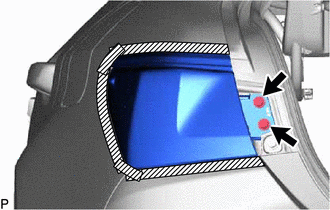
8. REMOVE REAR COMBINATION LIGHT COVER
(a) Disengage the 2 claws as shown in the illustration.
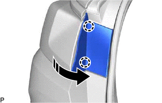
.png) | Remove in this Direction |
(b) Disengage the 2 claws and guide to remove the rear combination light cover as shown in the illustration.
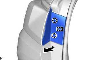
| | Remove in this Direction |
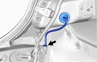
9. REMOVE REAR COMBINATION LIGHT LENS AND BODY
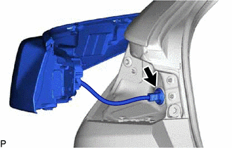
| (a) Disconnect the connector. |
|
(b) Apply protective tape around the rear combination light lens and body as shown in the illustration.
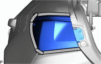
.png) | Protective Tape |
| (c) Remove the 2 screws. |
|
(d) Pull the rear combination light lens and body toward the rear of the vehicle as shown in the illustration to disengage the pin and 3 guides and separate the rear combination light lens and body.
NOTICE:
To prevent the rear combination light lens and body from falling when disengaging the pin and guides, make sure to hold the rear combination light lens and body.
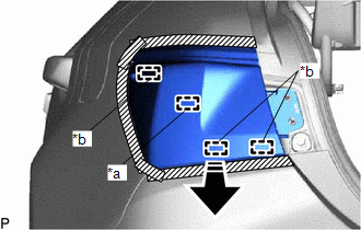
| *a | Pin |
| *b | Guide |
| | Remove in this Direction |
| (e) Disengage the grommet to remove the rear combination light lens and body. |
|
10. REMOVE REAR BUMPER ASSEMBLY (for TMMK Made)
for Single Type:
Click here
for Dual Type:
Click here
11. REMOVE REAR BUMPER UPPER RETAINER (for TMMK Made)
Click here
12. REMOVE REAR COMBINATION LIGHT ASSEMBLY (for TMMK Made)
READ NEXT:
 Inspection
INSPECTION PROCEDURE 1. INSPECT REAR COMBINATION LIGHT LENS AND BODY LH (for TMC Made) *a Component without harness connected (Rear Combination Light Lens and Body LH) (a) Apply auxiliary bat
Installation
INSTALLATION CAUTION / NOTICE / HINT HINT:
Use the same procedure for the RH side and LH side.
The following procedure is for the LH side.
PROCEDURE 1. INSTALL REAR COMBINATION LIGHT ASSEMBLY
SEE MORE:
Data List / Active Test
DATA LIST / ACTIVE TEST DATA LIST NOTICE: In the table below, the values listed under "Normal Condition" are reference values. Do not depend solely on these reference values when deciding whether a part is faulty or not. (a) Connect the Techstream to the DLC3. (b) Turn the power switch on (IG). (c)
Front Right Microphone Circuit Component Internal Failure (B1AA696,B1AA71C)
DESCRIPTION These DTCs are stored when a malfunction occurs in the No. 2 active noise control microphone system. DTC No. Detection Item DTC Detection Condition Trouble Area B1AA696 Front Right Microphone Circuit Component Internal Failure Stereo component equalizer assembly detects
