Lexus ES: Inspection
INSPECTION
PROCEDURE
1. INSPECT REAR COMBINATION LIGHT LENS AND BODY LH (for TMC Made)
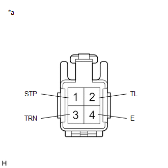
| *a | Component without harness connected (Rear Combination Light Lens and Body LH) |
(a) Apply auxiliary battery voltage to the rear combination light lens and body LH and check that the lights illuminate.
OK:
| Condition | Specified Condition |
|---|---|
| Auxiliary battery positive (+) → Terminal 2 (TL) Auxiliary battery negative (-) → Terminal 4 (E) | Taillight and side marker light illuminate |
| Auxiliary battery positive (+) → Terminal 1 (STP) Auxiliary battery negative (-) → Terminal 4 (E) | Stop light illuminates |
| Auxiliary battery positive (+) → Terminal 3 (TRN) Auxiliary battery negative (-) → Terminal 4 (E) | Turn signal light illuminates |
If the result is not as specified, replace the rear combination light lens and body LH.
2. INSPECT REAR COMBINATION LIGHT LENS AND BODY RH (for TMC Made)
| *a | Component without harness connected (Rear Combination Light Lens and Body RH) |
(a) Apply auxiliary battery voltage to the rear combination light lens and body RH and check that the lights illuminate.
OK:
| Condition | Specified Condition |
|---|---|
| Auxiliary battery positive (+) → Terminal 2 (TL) Auxiliary battery negative (-) → Terminal 4 (E) | Taillight and side marker light illuminate |
| Auxiliary battery positive (+) → Terminal 1 (STP) Auxiliary battery negative (-) → Terminal 4 (E) | Stop light illuminates |
| Auxiliary battery positive (+) → Terminal 3 (TRN) Auxiliary battery negative (-) → Terminal 4 (E) | Turn signal light illuminates |
If the result is not as specified, replace the rear combination light lens and body RH.
3. INSPECT REAR COMBINATION LIGHT ASSEMBLY LH (for TMMK Made)
| *a | Component without harness connected (Rear Combination Light Assembly LH) |
(a) Apply auxiliary battery voltage to the rear combination light assembly LH and check that the lights illuminate.
OK:
| Condition | Specified Condition |
|---|---|
| Auxiliary battery positive (+) → Terminal 2 (TL) Auxiliary battery negative (-) → Terminal 4 (E) | Taillight and side marker light illuminate |
| Auxiliary battery positive (+) → Terminal 1 (STP) Auxiliary battery negative (-) → Terminal 4 (E) | Stop light illuminates |
| Auxiliary battery positive (+) → Terminal 3 (TRN) Auxiliary battery negative (-) → Terminal 4 (E) | Turn signal light illuminates |
If the result is not as specified, replace the rear combination light assembly LH.
4. INSPECT REAR COMBINATION LIGHT ASSEMBLY RH (for TMMK Made)
| *a | Component without harness connected (Rear Combination Light Assembly RH) |
(a) Apply auxiliary battery voltage to the rear combination light assembly RH and check that the lights illuminate.
OK:
| Condition | Specified Condition |
|---|---|
| Auxiliary battery positive (+) → Terminal 2 (TL) Auxiliary battery negative (-) → Terminal 4 (E) | Taillight and side marker light illuminate |
| Auxiliary battery positive (+) → Terminal 1 (STP) Auxiliary battery negative (-) → Terminal 4 (E) | Stop light illuminates |
| Auxiliary battery positive (+) → Terminal 3 (TRN) Auxiliary battery negative (-) → Terminal 4 (E) | Turn signal light illuminates |
If the result is not as specified, replace the rear combination light assembly RH.
READ NEXT:
 Installation
INSTALLATION CAUTION / NOTICE / HINT HINT:
Use the same procedure for the RH side and LH side.
The following procedure is for the LH side.
PROCEDURE 1. INSTALL REAR COMBINATION LIGHT ASSEMBLY
Components
COMPONENTS ILLUSTRATION *A w/ Power Trunk Lid System - - *1 LUGGAGE COMPARTMENT DOOR COVER *2 LUGGAGE LOCK CONTROL CABLE PLATE *3 SWITCH BEZEL - - ILLUSTRATION *1
SEE MORE:
DC/DC Converter Voltage Sensor "A"(VL) Circuit Voltage Above Threshold (P0E5717)
DTC SUMMARY MALFUNCTION DESCRIPTION If an overvoltage malfunction occurs in the motor inverter or generator inverter, the motor generator control ECU (MG ECU) detects the malfunction and stores this DTC. The cause of this malfunction may be one of the following: Area Main Malfunction Descriptio
Data List / Active Test
DATA LIST / ACTIVE TEST DATA LIST NOTICE: In the table below, the values listed under "Normal Condition" are reference values. Do not depend solely on these reference values when deciding whether a part is faulty or not. HINT: Using the Techstream to read the Data List allows the values or states of
