Lexus ES: Removal
REMOVAL
CAUTION / NOTICE / HINT
The necessary procedures (adjustment, calibration, initialization or registration) that must be performed after parts are removed and installed, or replaced during headlight ECU sub-assembly removal/installation are shown below.
Necessary Procedure After Parts Removed/Installed/Replaced (for HV Model)| Replaced Part or Performed Procedure | Necessary Procedure | Effect/Inoperative Function when Necessary Procedure not Performed | Link |
|---|---|---|---|
| *1: for LED type turn signal light | |||
| Front bumper assembly |
|
| |
| Front television camera view adjustment | Panoramic View Monitor System (for HV Model) | for Initialization for Calibration | |
| Headlight ECU sub-assembly LH |
| Lighting system (for HV Model) | |
| Replaced Part or Performed Procedure | Necessary Procedure | Effect/Inoperative Function when Necessary Procedure not Performed | Link |
|---|---|---|---|
| *1: for LED type turn signal light | |||
| Front bumper assembly |
|
| |
| Front television camera view adjustment | Panoramic View Monitor System (for Gasoline Model) | for Initialization for Calibration | |
| Headlight ECU sub-assembly LH |
| Lighting System (for Gasoline Model) | |
HINT:
- Use the same procedure for the RH side and LH side.
- The following procedure is for the LH side.
PROCEDURE
1. REMOVE HEADLIGHT ASSEMBLY
for LED Type Turn Signal Light:
Click here .gif)
for Bulb Type Turn Signal Light:
Click here
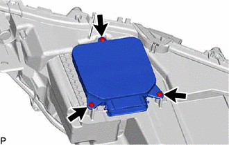
2. REMOVE HEADLIGHT ECU SUB-ASSEMBLY
NOTICE:
- Make sure to replace the headlight gasket with a new one. Failure to do so may cause water ingress.
- If the headlight ECU sub-assembly has been struck or dropped, replace it with a new one.
| (a) Remove the 3 screws. |
|
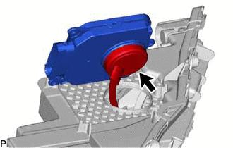
| (b) Separate the connector cover from the headlight ECU sub-assembly. |
|
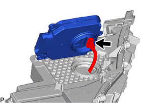
(c) for Single Beam Headlight:
| (1) Disconnect the connector to remove the headlight ECU sub-assembly. |
|
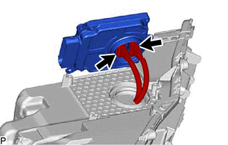
(d) for Triple Beam Headlight:
| (1) Disconnect the 2 connectors to remove the headlight ECU sub-assembly. |
|
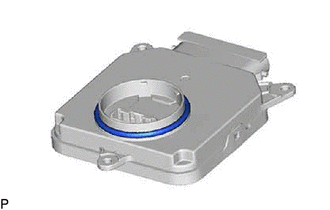
3. REMOVE HEADLIGHT GASKET
NOTICE:
Make sure to replace the headlight gasket with a new one. Failure to do so may cause water ingress.
| (a) Remove the headlight gasket. |
|
READ NEXT:
 Installation
INSTALLATION CAUTION / NOTICE / HINT HINT:
Use the same procedure for the RH side and LH side.
The following procedure is for the LH side.
PROCEDURE 1. INSTALL HEADLIGHT GASKET (a) Install a n
Components
COMPONENTS ILLUSTRATION *1 REAR HEIGHT CONTROL SENSOR SUB-ASSEMBLY LH - - N*m (kgf*cm, ft.*lbf): Specified torque - -
SEE MORE:
Active Grille Air Shutter "A" Actuator Stuck Closed (P059F73,...,P05B131)
DESCRIPTION These DTCs are stored when a malfunction occurs in the grille shutter system. DTC No. Detection Item Note P059F73 Active Grille Air Shutter "A" Actuator Stuck Closed The ECM stores this DTC as an SFI system DTC* P05A072 Active Grille Air Shutter "A" Actuator Stuck Op
Installation
INSTALLATION CAUTION / NOTICE / HINT HINT:
Use the same procedure for the RH side and LH side.
The following procedure is for the LH side.
PROCEDURE 1. INSTALL REAR SUSPENSION ARM BRACKET (a) Temporarily install the rear suspension arm bracket to the rear trailing arm assembly with the bo
