Lexus ES: Installation
INSTALLATION
CAUTION / NOTICE / HINT
HINT:
- Use the same procedure for the RH side and LH side.
- The following procedure is for the LH side.
PROCEDURE
1. INSTALL REAR SUSPENSION ARM BRACKET
| (a) Temporarily install the rear suspension arm bracket to the rear trailing arm assembly with the bolt and nut. NOTICE: Insert the bolt from the inside of the vehicle. |
|
.png)
| (b) Position the rear trailing arm assembly as shown in the illustration. Reference Length (A):
|
|
.png)
(c) Fully tighten the nut.
Torque:
120 N·m {1224 kgf·cm, 89 ft·lbf}
2. INSTALL REAR SUSPENSION ARM COVER
(a) Engage the 4 claws and install the rear suspension arm cover.
3. INSTALL REAR TRAILING ARM ASSEMBLY
(a) Using a transmission jack and a wooden block, support the rear No. 2 suspension arm assembly.
NOTICE:
- When jacking up the rear No. 2 suspension arm assembly, be sure to jack it up slowly.
- Make sure to perform this operation with the vehicle kept as low as possible.
(b) Install the rear trailing arm assembly to the vehicle with the 4 bolts.
Torque:
90 N·m {918 kgf·cm, 66 ft·lbf}
(c) for 2WD:
(1) Install the rear trailing arm assembly to the rear axle carrier sub-assembly with the 2 bolts.
Torque:
135 N·m {1377 kgf·cm, 100 ft·lbf}
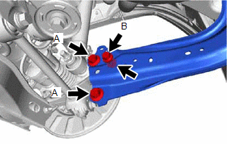
(d) for AWD:
| (1) Install the rear trailing arm assembly to the rear axle carrier sub-assembly with the 3 bolts and nut. Torque: Bolt (A) : 135 N·m {1377 kgf·cm, 100 ft·lbf} Bolt (B) : 75 N·m {765 kgf·cm, 55 ft·lbf} |
|
4. INSTALL NO. 2 PARKING BRAKE WIRE ASSEMBLY (w/o AVS)
| (a) Install the No. 2 parking brake wire assembly to the rear trailing arm assembly with the nut. Torque: 15.5 N·m {158 kgf·cm, 11 ft·lbf} |
|
.png)
(b) Engage the 2 clamps.
5. INSTALL NO. 2 PARKING BRAKE WIRE ASSEMBLY (w/ AVS)
| (a) Install the No. 2 parking brake wire assembly to the rear trailing arm assembly with the nut. Torque: 15.5 N·m {158 kgf·cm, 11 ft·lbf} |
|
.png)
(b) Engage the clamp.
| (c) Engage the guide and install the wire harness bracket. |
|
.png)
(d) Install the nut.
Torque:
8.5 N·m {87 kgf·cm, 75 in·lbf}
(e) Engage the clamp and install the No. 2 parking brake wire assembly to the wire harness bracket.
| (f) Connect the connector. |
|
.png)
6. INSTALL REAR STABILIZER LINK ASSEMBLY (for 2WD)
Click here .gif)
7. INSTALL NO. 1 FLOOR UNDER COVER (for Gasoline Model AWD)
(a) for RH Side:
| (1) Install the No. 1 floor under cover with the 2 grommets (B) and clip (C). |
|
.png)
(2) Install the bolt and 2 clips (A).
Torque:
Bolt :
7.5 N·m {76 kgf·cm, 66 in·lbf}
8. INSTALL NO. 2 FLOOR UNDER COVER (for Gasoline Model AWD)
(a) for LH Side:
| (1) Install the No. 2 floor under cover with the 2 grommets (B) and 2 clips (C). |
|
.png)
(2) Install the bolts and 2 clips (A).
Torque:
Bolt :
7.5 N·m {76 kgf·cm, 66 in·lbf}
9. INSTALL NO. 1 FLOOR UNDER COVER (for HV Model)
| (a) for RH Side: (1) Install the No. 1 floor under cover with the 2 grommets (B). (2) Install the bolt and clip (A). Torque: Bolt : 7.5 N·m {76 kgf·cm, 66 in·lbf} |
|
.png)
10. INSTALL NO. 2 FLOOR UNDER COVER (for HV Model)
| (a) for LH Side: (1) Install the No. 2 floor under cover with the 2 grommets (B) and clip (C). (2) Install the bolt and clip (A). Torque: Bolt : 7.5 N·m {76 kgf·cm, 66 in·lbf} |
|
.png)
11. INSTALL NO. 1 FLOOR UNDER COVER (for Gasoline Model 2WD)
(a) for RH Side:
Click here
12. INSTALL NO. 2 FLOOR UNDER COVER (for Gasoline Model 2WD)
(a) for LH Side:
Click here
13. INSTALL REAR WHEEL
Click here
14. INSPECT AND ADJUST REAR WHEEL ALIGNMENT
Click here
15. PERFORM INITIALIZATION
for HV Model:| *1: for LED type turn signal light | |
| |
| Parking Assist Monitor System | |
| Panoramic View Monitor System | |
| Lighting System*1 | |
| *1: for LED type turn signal light | |
| |
| Parking Assist Monitor System | |
| Panoramic View Monitor System | |
| Lighting System*1 | |
READ NEXT:
 Components
COMPONENTS ILLUSTRATION *1 REAR SUSPENSION MEMBER SUB-ASSEMBLY *2 REAR UPPER CONTROL ARM ASSEMBLY LH *3 REAR UPPER CONTROL ARM ASSEMBLY RH - - Tightening torque for "Major a
Components
COMPONENTS ILLUSTRATION *A for 2WD - - *1 REAR SUSPENSION MEMBER SUB-ASSEMBLY *2 REAR UPPER CONTROL ARM ASSEMBLY LH *3 REAR UPPER CONTROL ARM ASSEMBLY RH - - Tight
SEE MORE:
Calibration
CALIBRATION NOTICE:
Initial AWD functions such as acceleration are sometimes affected unless backup memory is cleared.
When the yaw rate and acceleration sensor (airbag ECU assembly) is replaced, Reset Memory must be performed.
RESET MEMORY (a) Turn the engine switch off. (b) Connect the Tec
Customize Parameters
CUSTOMIZE PARAMETERS CUSTOMIZE POWER TILT AND POWER TELESCOPIC STEERING COLUMN SYSTEM HINT: The following items can be customized. NOTICE:
When the customer requests a change in a function, first make sure that the function can be customized.
Record the current settings before customizing.
(
