Lexus ES: Removal
REMOVAL
CAUTION / NOTICE / HINT
The necessary procedures (adjustment, calibration, initialization, or registration) that must be performed after parts are removed and installed, or replaced during luggage closer motor assembly removal/installation are shown below.
Necessary Procedure After Parts Removed/Installed/Replaced (for Gasoline Model)| Replaced Part or Performed Procedure | Necessary Procedure | Effect/Inoperative Function When Necessary Procedures are not Performed | Link |
|---|---|---|---|
| Luggage closer motor assembly | Initialize power trunk lid system | Power Trunk Lid System | |
| Replaced Part or Performed Procedure | Necessary Procedure | Effect/Inoperative Function When Necessary Procedures are not Performed | Link |
|---|---|---|---|
| Luggage closer motor assembly | Initialize power trunk lid system | Power Trunk Lid System | |
HINT:
- Use the same procedure for the RH side and LH side.
- The following procedure is for the LH side.
PROCEDURE
1. REMOVE LUGGAGE COMPARTMENT FLOOR MAT
Click here .gif)
2. REMOVE SPARE WHEEL COVER TRAY
Click here
3. REMOVE REAR FLOOR FINISH PLATE
Click here
4. REMOVE LUGGAGE LOCK CONTROL CABLE PLATE
Click here
5. REMOVE SWITCH BEZEL
Click here
6. REMOVE LUGGAGE COMPARTMENT DOOR COVER
Click here
7. REMOVE LUGGAGE COMPARTMENT DOOR HINGE COVER RH
HINT:
Use the same procedure as for the LH side.
Click here
8. REMOVE LUGGAGE COMPARTMENT TRIM COVER RH
Click here
9. REMOVE LUGGAGE COMPARTMENT TRIM INNER COVER RH
Click here
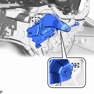
10. REMOVE LUGGAGE CLOSER MOTOR ASSEMBLY
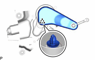
| (a) Remove the nut. |
|
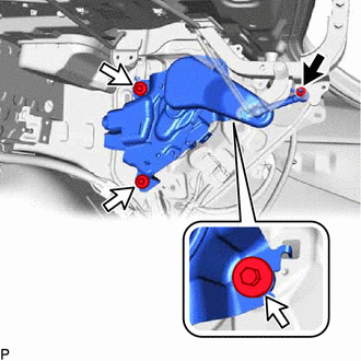
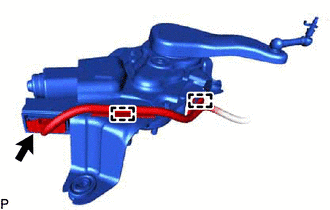
(b) Remove the 3 bolts.
| (c) Disengage the 2 guides. |
|
| (d) Disengage the 2 clamps. |
|
(e) Disconnect the connector to remove the luggage closer motor assembly.
11. REMOVE DECK SIDE TRIM COVER RH
| (a) Disengage the clip and remove the deck side trim cover RH. |
|
READ NEXT:
 Installation
INSTALLATION PROCEDURE 1. INSTALL DECK SIDE TRIM COVER RH (a) Engage the clip to install the deck side trim cover RH. 2. INSTALL LUGGAGE CLOSER MOTOR ASSEMBLY (a) Connect the connector. (b) Engage the
SEE MORE:
Installation
INSTALLATION PROCEDURE 1. INSTALL FLOW SHUTTING VALVE (WATER BY-PASS HOSE ASSEMBLY) (a) Connect the flow shutting valve (water by-pass hose assembly) to the transmission oil cooler and slide the clip to secure it. *a 2 to 7 mm (0.0787 to 0.276 in.) *b Paint Mark *c 45° (Tabs of Clip
Touch Pad Sensor Malfunction (B1559)
DESCRIPTION This DTC is stored if the remote touch (remote operation controller assembly) detects a malfunction in itself, such as internal hardware failure or remote touch screen sensor malfunction. DTC No. Detection Item DTC Detection Condition Trouble Area B1559 Touch Pad Sensor Ma
