Lexus ES: Removal
REMOVAL
PROCEDURE
1. CHANGE POWER TILT AND POWER TELESCOPIC STEERING COLUMN SYSTEM SETTINGS (for Power Tilt and Power Telescopic Steering Column)
Click here .gif)
2. REMOVE LOWER STEERING COLUMN COVER SUB-ASSEMBLY
NOTICE:
Removing the lower steering column cover sub-assembly in the incorrect order will cause the parts to break.
(a) for Manual Tilt and Manual Telescopic Steering Column:
(1) Release the tilt and telescopic lever and fully extend and lower the steering column assembly.
(2) Lock the tilt and telescopic lever.
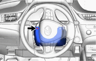
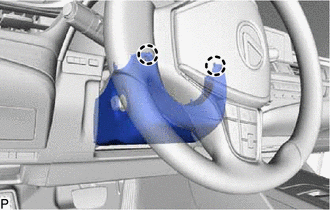
| (b) Turn the steering wheel assembly to the left and remove the screw. |
|
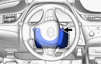
| (c) Turn the steering wheel assembly to the right and remove the screw. |
|
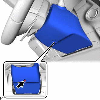
| (d) Remove the screw. |
|
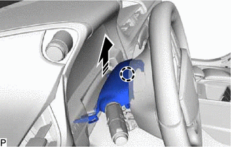
(e) Push the lower steering column cover sub-assembly and disengage the 2 claws as shown in the illustration.
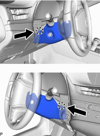
.png) | Push |
| (f) Disengage the 2 claws to remove the lower steering column cover sub-assembly. |
|
3. REMOVE UPPER STEERING COLUMN COVER
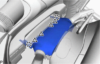
(a) Disengage the claw to separate the upper steering column cover as shown in the illustration.
.png) | Remove in this Direction |
| (b) Disengage the 2 claws and 4 clips to remove the upper steering column cover. |
|
4. REMOVE WINDSHIELD WIPER SWITCH ASSEMBLY
(a) Using a screwdriver with its tip wrapped with protective tape, disengage the claw and remove the windshield wiper switch assembly as shown in the illustration.
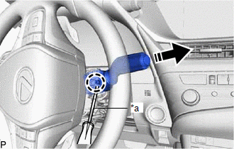
| *a | Protective Tape |
| | Remove in this Direction |
NOTICE:
If the claw is pulled with excessive force, it may break.
READ NEXT:
 Inspection
INSPECTION PROCEDURE 1. INSPECT WINDSHIELD WIPER SWITCH ASSEMBLY (w/ Auto Wiper System) (a) Measure the resistance according to the value(s) in the table below. *A for Type A *B for Type B
Installation
INSTALLATION PROCEDURE 1. INSTALL WINDSHIELD WIPER SWITCH ASSEMBLY (a) Engage the claw to install the windshield wiper switch assembly as shown in the illustration. Install in this Direction
Vehicle Interior
h1 {color:red;} h2 {color:blue;} h3 {color:green;}
SEE MORE:
How To Proceed With Troubleshooting
CAUTION / NOTICE / HINT HINT:
Use the following procedure to troubleshoot the sliding roof system.
*: Use the Techstream.
PROCEDURE 1. VEHICLE BROUGHT TO WORKSHOP
NEXT 2. CUSTOMER PROBLEM ANALYSIS HINT:
In troubleshooting, confirm that the problem sympto
Parts Location
PARTS LOCATION ILLUSTRATION *1 INSTRUMENT PANEL JUNCTION BLOCK ASSEMBLY - DCM FUSE - ECU-IG2 NO. 3 FUSE *2 DLC3 *3 AIRBAG ECU ASSEMBLY *4 DCM (TELEMATICS TRANSCEIVER) - MOBILEPHONE BATTERY ILLUSTRATION *1 FRONT NO. 2 SPEAKER ASSEMBLY (RH) *2 TELEPHONE MICROPHONE ASSE
